
Create a MicroBlaze, Test the UART in SDK, and Boot Linux using 2019.1 Vivado and PetaLinux Tools
![]()
This post contains everything needed to create a MicroBlaze design and boot Linux on it over JTAG. It also contains links to all the IP documentation and how to smoke-test a design before using it.
Versions Used
2019.1 Vivado, PetaLinux Tools, and XSDK
VMWare Workstation 14 Player running Ubuntu 16.04.5 LTS running on Windows 10
Update Vivado 2019.1
Note
I needed this patch to build the bitstream.
Steps
Step #1: Download the patch at:
https://www.xilinx.com/support/answers/72956.html#:~:text=You%20will%20see%20a%20MIG,will%20not%20generate%20a%20response.
Step #2: Exit Vivado 2019.1
Note: commands assume Vivado is installed at:
/tools/Xilinx/Vivado/2019.1/bin/vivado
Step #3: Run
mkdir /tools/Xilinx/Vivado/2019.1/patches
mkdir /tools/Xilinx/Vivado/2019.1/patches/AR72956
pushd /tools/Xilinx/Vivado/2019.1/patches/AR72956
unzip ~/Downloads/AR72956_vivado_2019_1_preliminary_rev1.zip
Step #4: Restart Vivado 2019.1
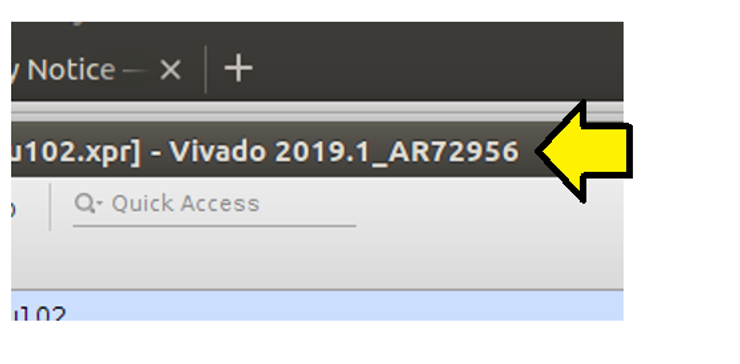
Step #5: Check that the Patch Applied
Enter in the Design
Notes
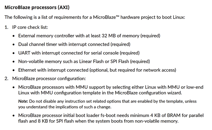
For Linux to boot on MicroBlaze
Page 19 of https://www.xilinx.com/support/documentation/sw_manuals/xilinx2019_1/ug1144-petalinux-tools-reference-guide.pdf lists the requirements to run Linux on a MicroBlaze. I’ve left out both the Non-volatile memory and Ethernet in this design. Also, I use an AXI Timer, not a Dual channel timer.
Steps
Step #1: Run Vivado 2019.1
Step #2: File > Project > New
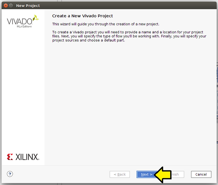
Step #3: Click Next on the Create New Vivado Project window
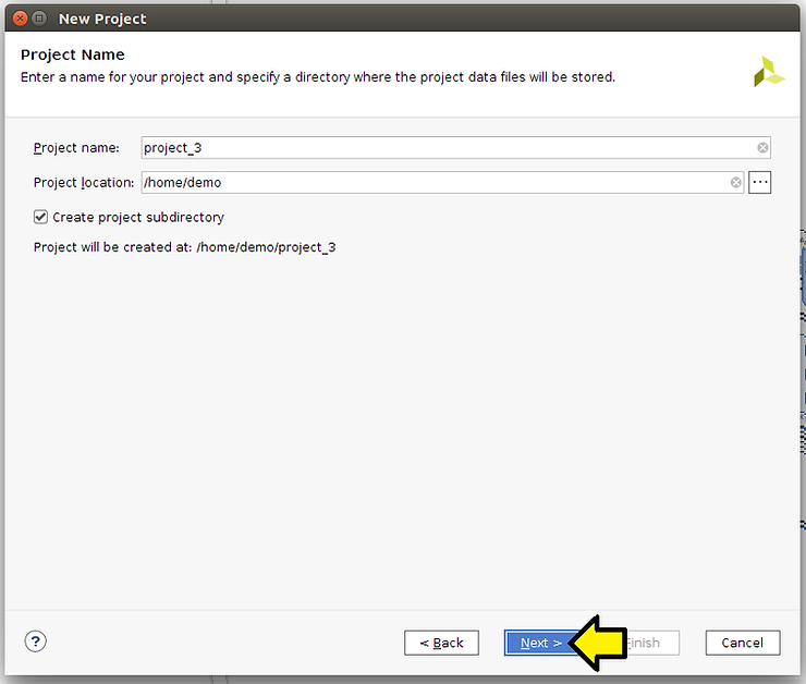
Step # 3.1: Click Next in the Project Name window
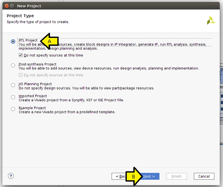
Step #3.2: (A) Click RTL Project and (B) click Next
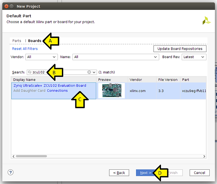
Step # 3.3: (A) Click Boards, (B) enter zcu102, (C) click on the line, and (D) click Next
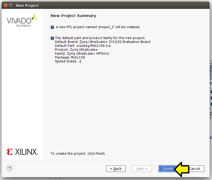
Step #3.4: Click Finish
Create the Block Design
Steps
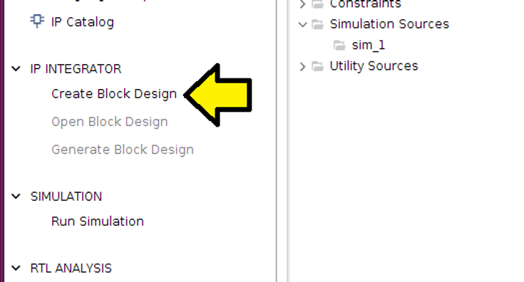
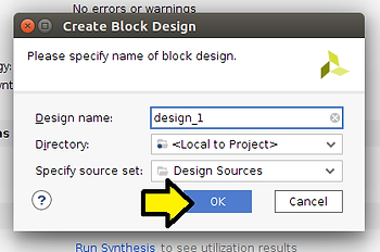
Step #1: Click Create Block Design
Step #1.1: Click OK
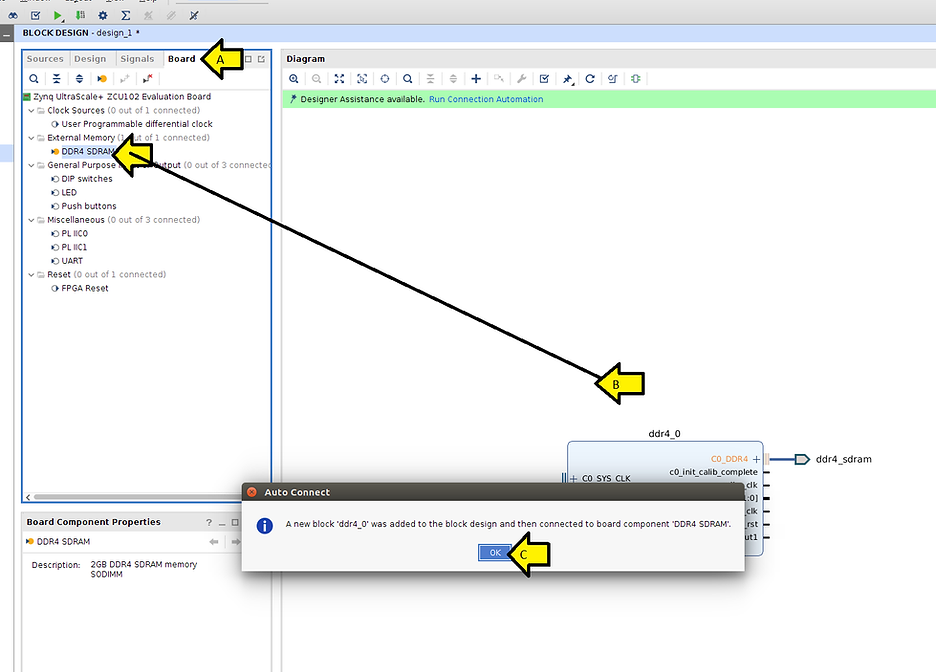
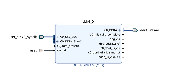
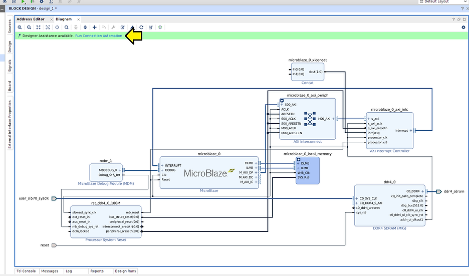
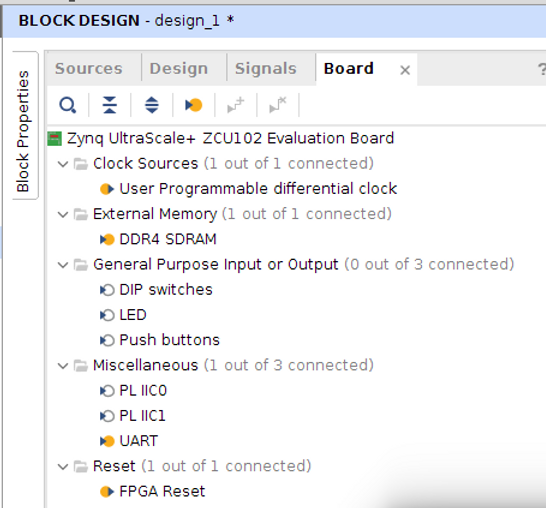
Step #2: (A) Click Board, (B) Pull DDR4 SDRAM to the Diagram, and (C) click OK
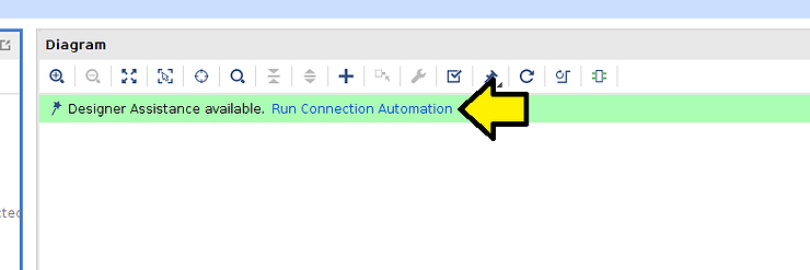
Step #3: Click Run Connection Automation
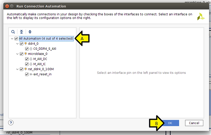
Step #3.1: (A) Check all checkboxes and (B) click OK
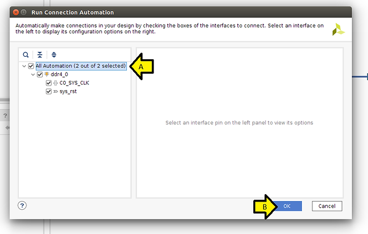
You should see:
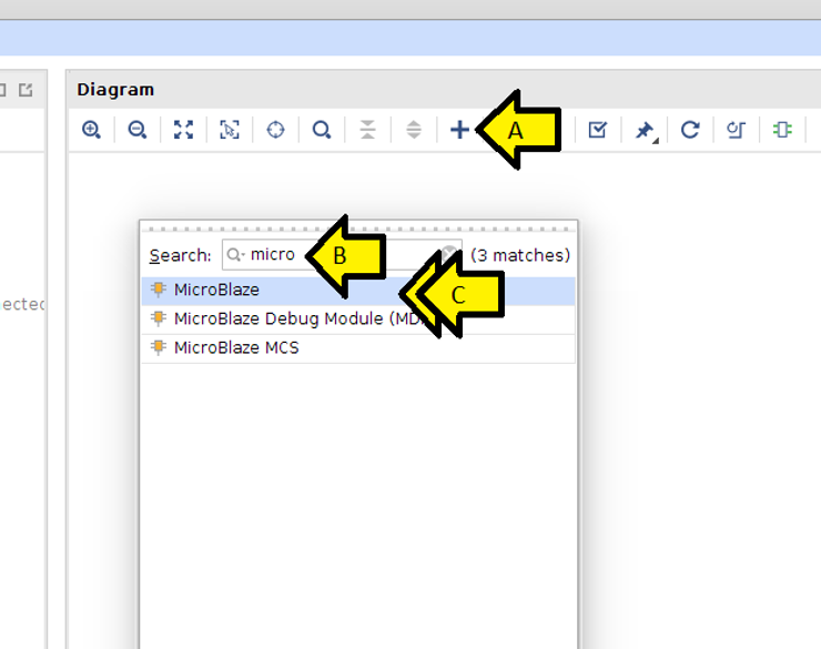
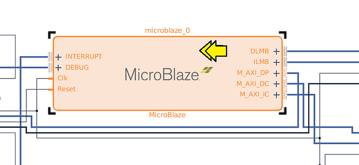
Step #4: (A) Click +, (B) type micro, and (C) double-click MicroBlaze
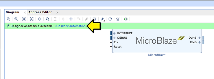
Step #5: Click Run Block Automation
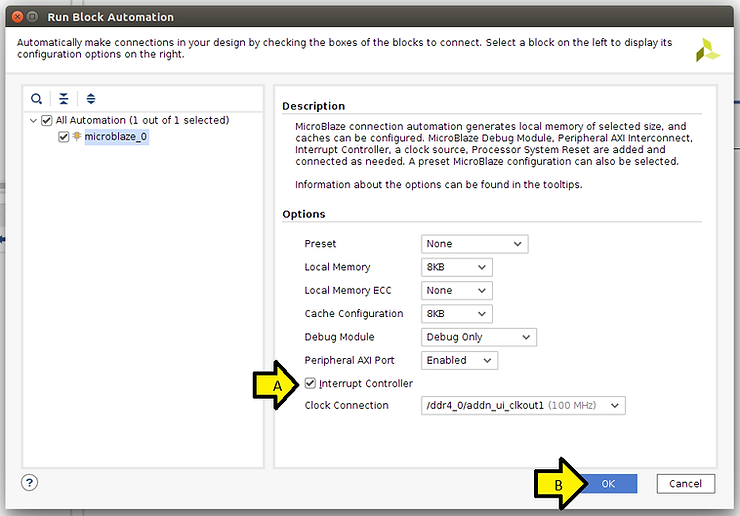
Step #6: (A) Check the Interrupt Controller checkbox and (B) click OK
Note: we select Linux with MMU later during IP customization
Note 2: this ^^^ step is how you get microblaze_0_local_memory
Step #7: Click Run Connection Automation
Step #7.1: (A) Select all checkboxes and (B) click OK
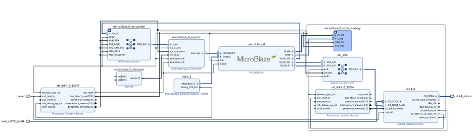
You should see:
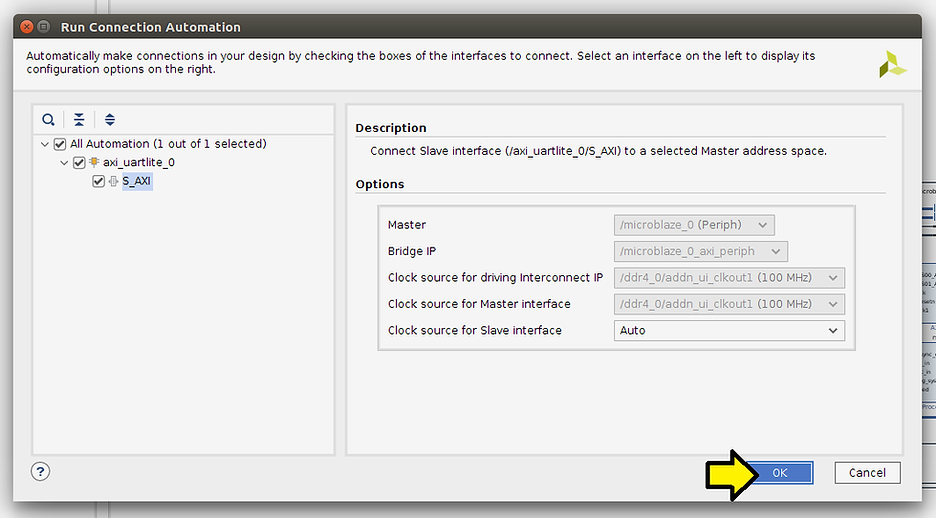
Step #7.2: (A) Click Board, (B) click and drag UART, (C) click OK, and (D) click Run Connection Automation
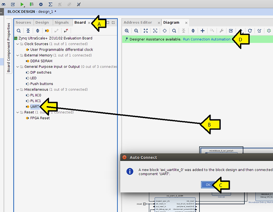
Step #7.3: Click OK
You should see:
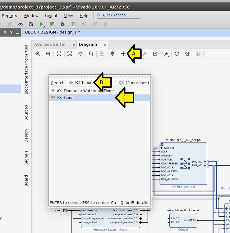
Step #8: (A) Click +, (B) Type AXI Timer, and (C) click AXI Timer
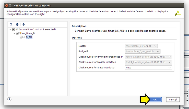
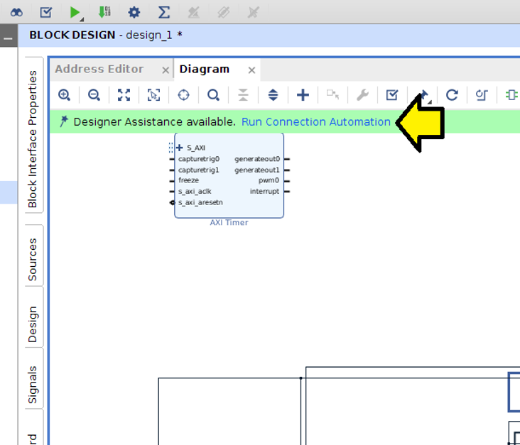
Step #8.1: Click Run Connection Automation
Step # 8.2: Click OK
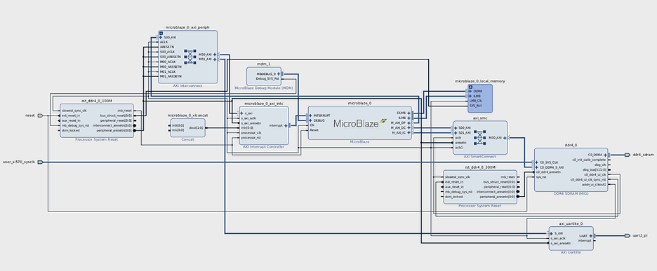
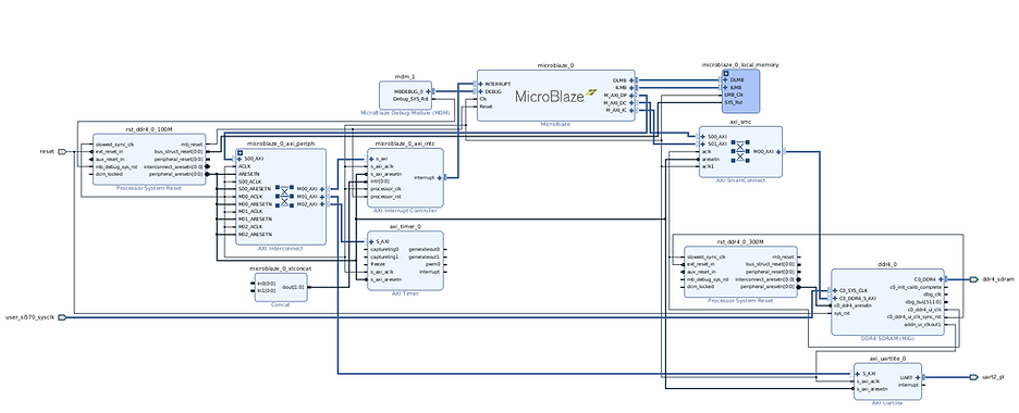
You should see:
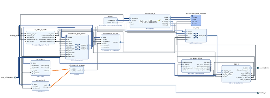
Step #9: Connect the axi_timer_0 interrupt and the axi_uartlite_0 interrupt pins to the microblaze_0_xlconcat
Note: you will still see the UART output in XSDK without this, and Linux will run, but you won’t see any UART output.
Customize the MicroBlaze IP
Steps
Step #1: Double click on the microblaze_0 instance of the MicroBlaze
Step #1.1: (A) Select Linux with MMU and (B) click OK
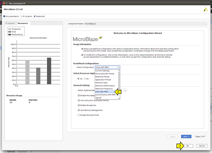
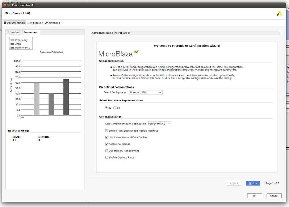
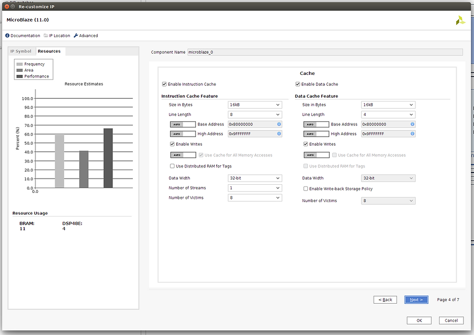
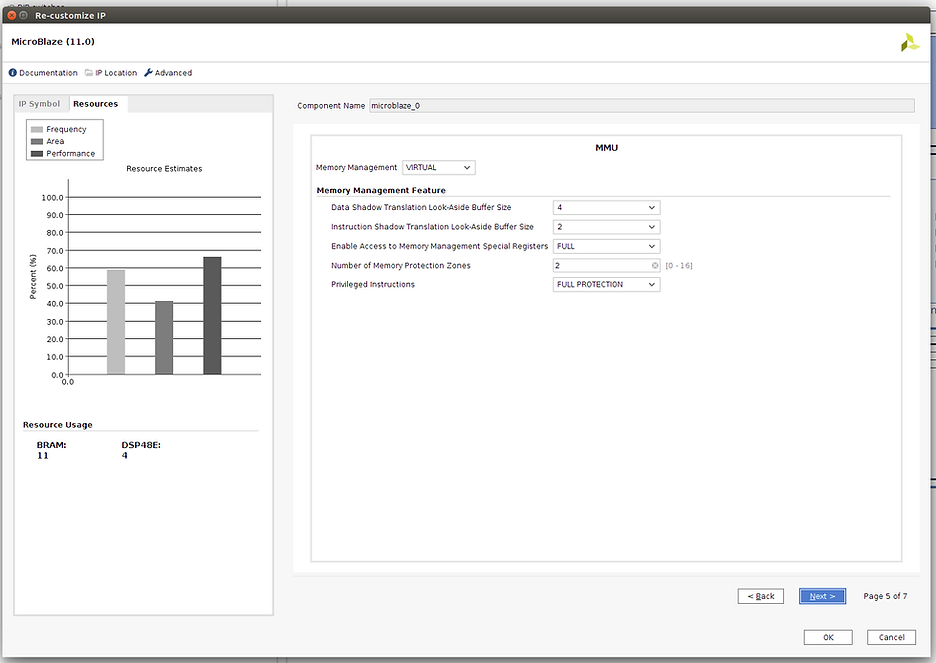
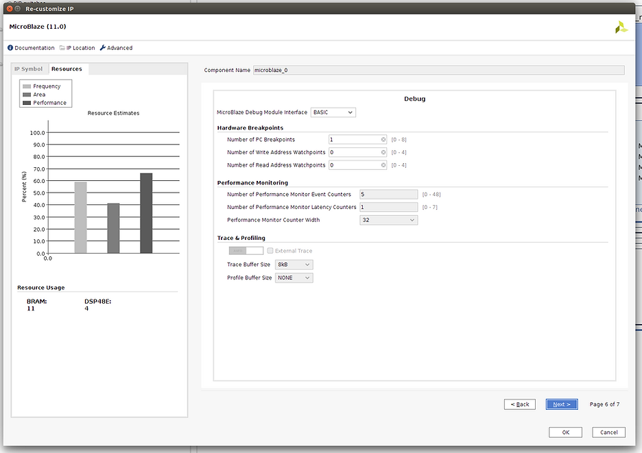
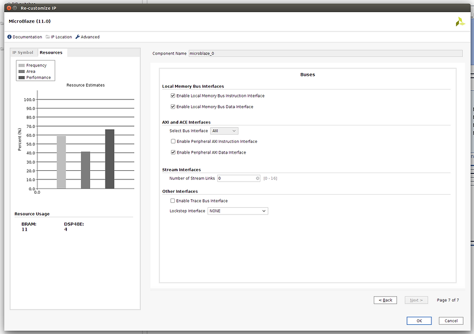
You only need to set Linux with MMU. Here are the other pages as a reference.
Page 1
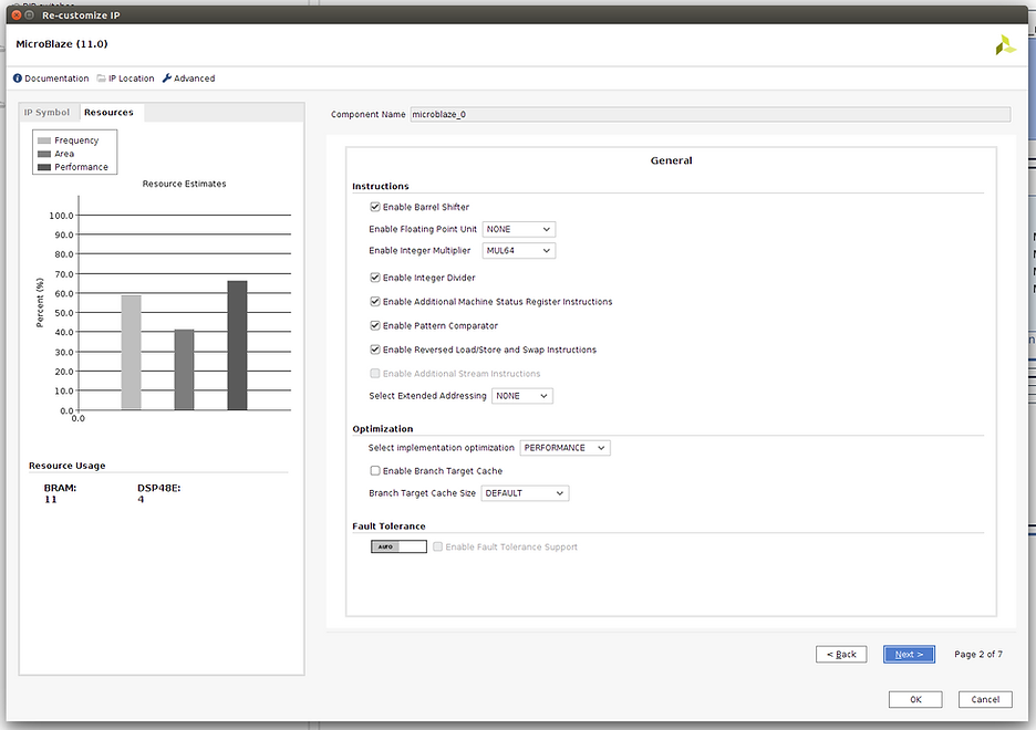
Page 2
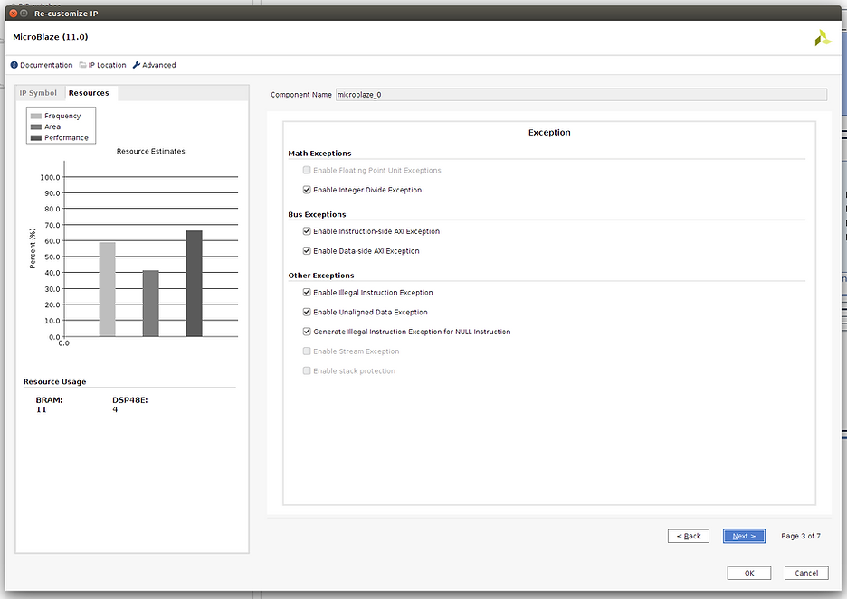
Page 3
Page 4
Page 5
Page 6
Page 7
Get Ready to Create the Bitstream
Steps
Step #1: Check the Board
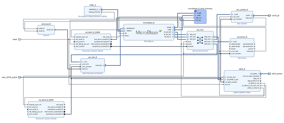
Step #2: Check the full design
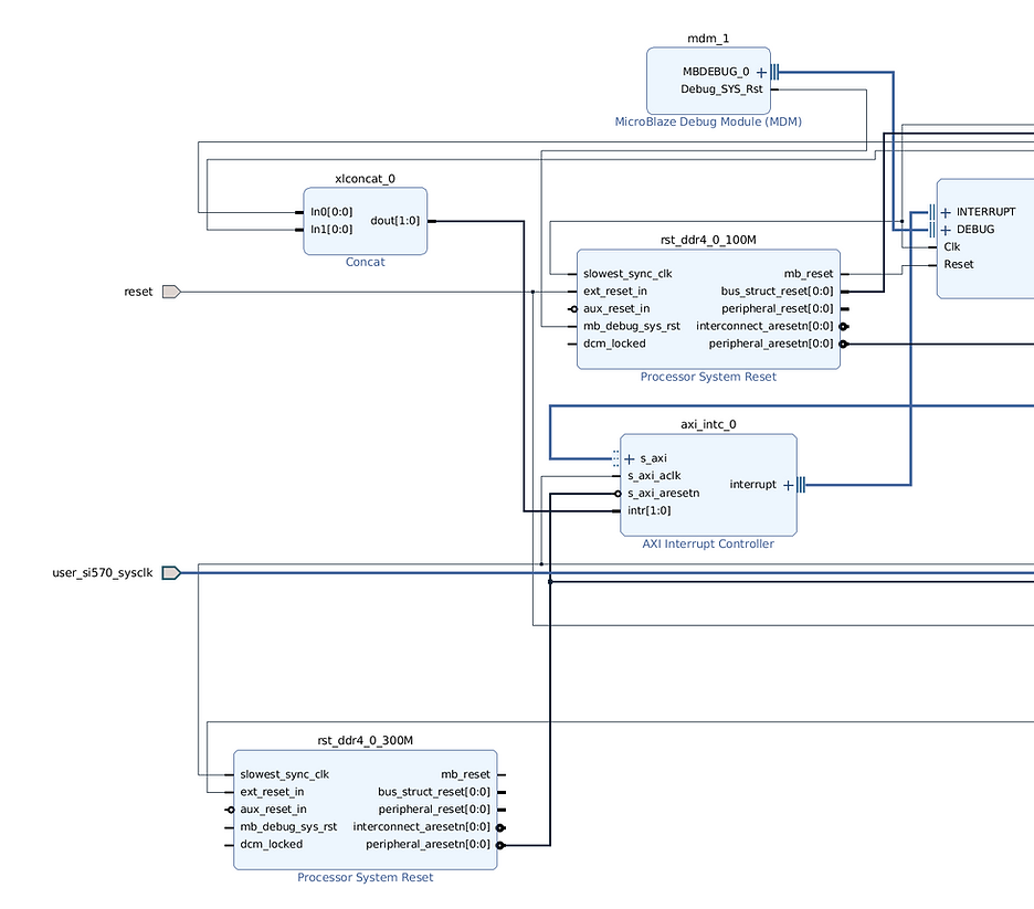
Step #2.1: Zoom into the left side
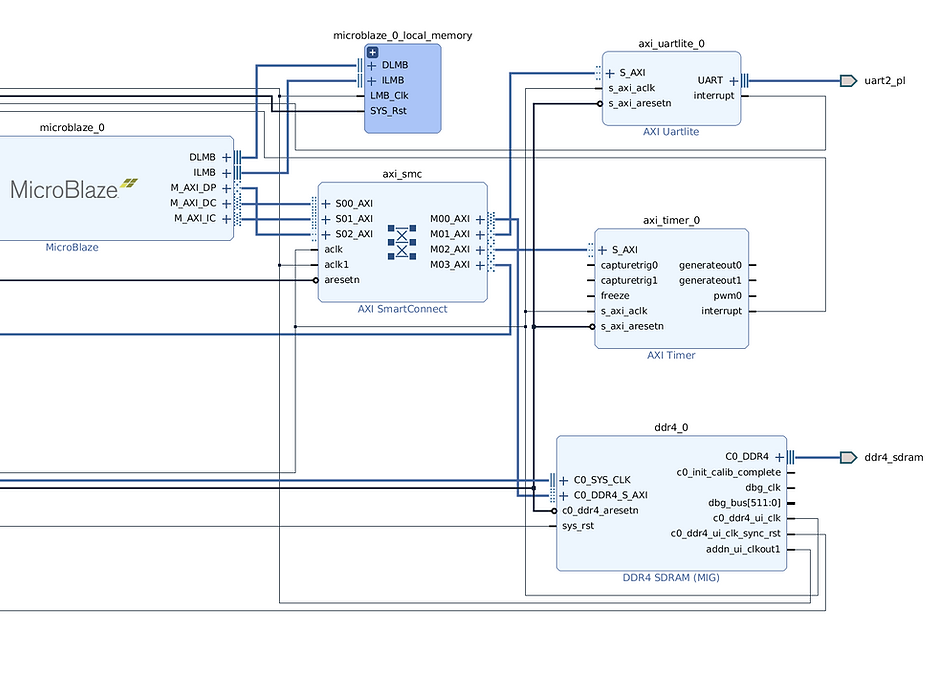
Step #2.2: Zoom into the right side
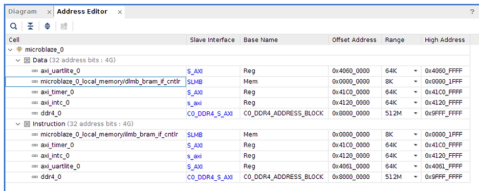
Step #3: Check the Address Editor
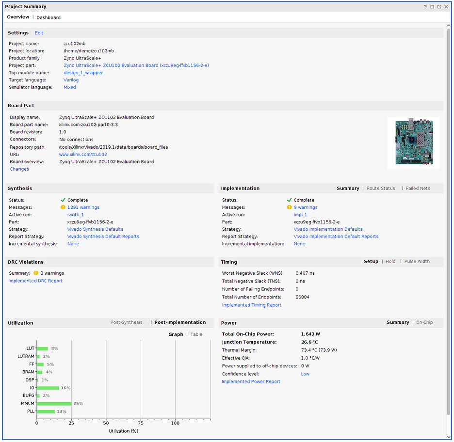
Step #4: Check the Project Summary
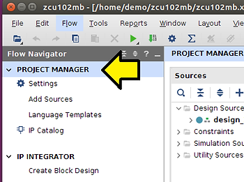
Step #4.1: Click PROJECT MANAGER to get the Project Summary
You should see something like:
Create the Bitstream
Steps
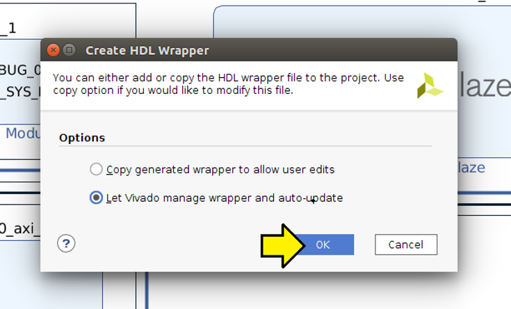
Step #1: Create the HDL Wrapper
Step #1.1: (A) Click Sources, (B) right-click design_1 (design_1_hd), and (C) click Create HDL Wrapper…
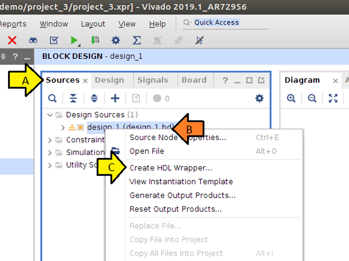
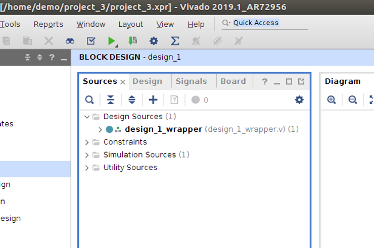
Step #1.2: Leave Let Vivado manage wrapper and auto-update selected and click OK
You should see:
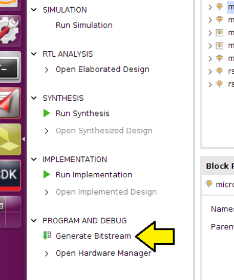
Step #2: Click Generate Bitstream
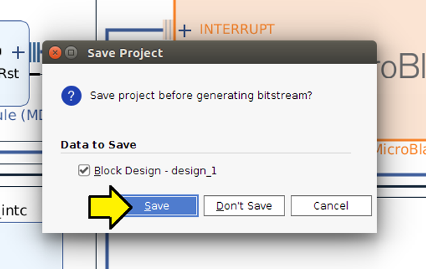
Step #2.1: Click Save
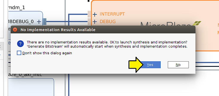
Step #2.2: Click Yes on the No Implementation Results Available notification box
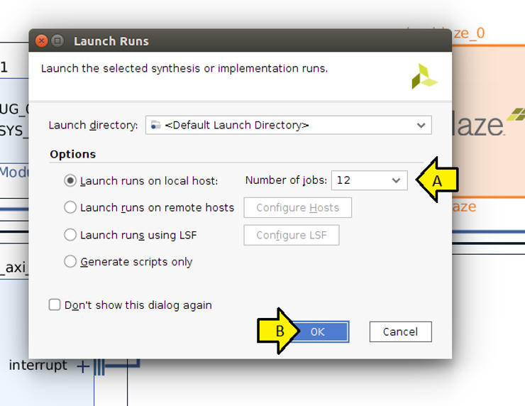
Step #2.3: Select as many cores as you can and click OK
Note: this can take 1 to 2 hours to run
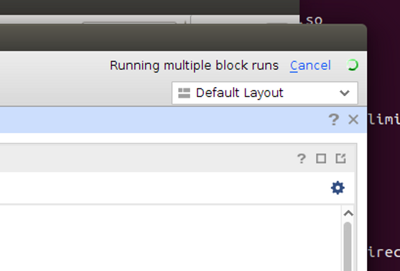
Note 2: You should see a status indicator in the upper right-hand corner
Program the Bitstream
Steps
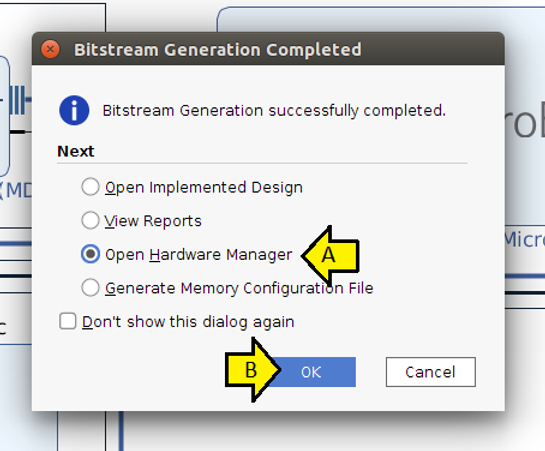
Step #1: (A) Select Open Hardware Manager and (B) click OK
Step #2: Plug the UART and JTAG USB cables into the board…
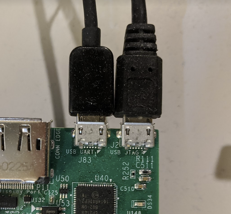
Step #2.1: …and into a hub…
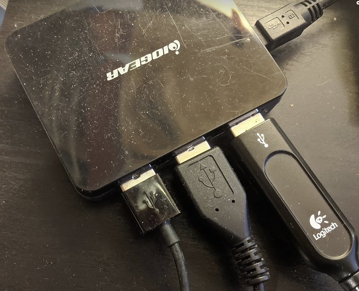
Step #2.2: …which is plugged into the computer
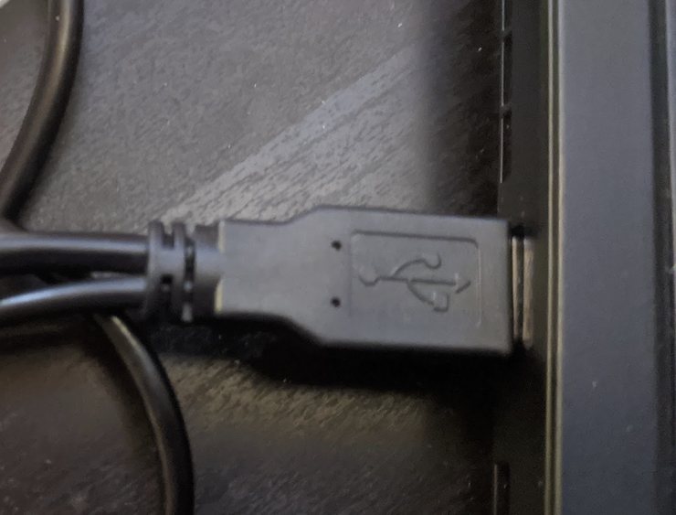
Important note: using a hub is a good way to connect the JTAG and UART USB devices to a VM. It has worked for VMWare and VirtualBox.
Step #3: Make sure the SW6 is set to JTAG boot the ZCU102
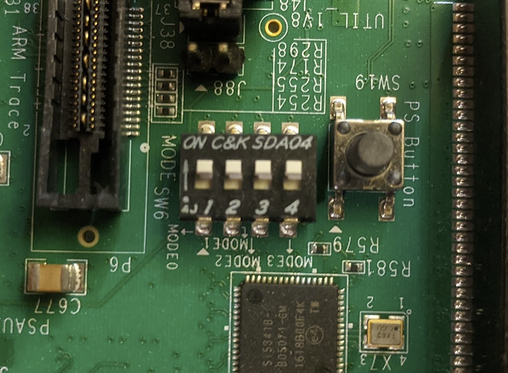
Step #4: Turn on the ZCU102
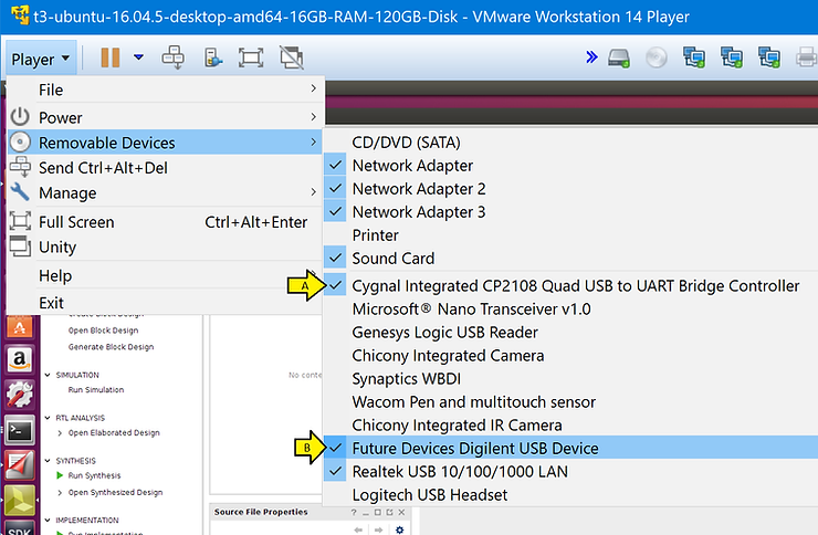
Step #5: Ensure that the Cygnal Integrated CP2108 Quad USB to UART Bridge Controller is enabled and Future Devices Digilent USB Device is enabled.
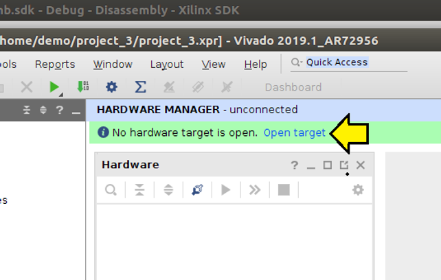
Step #6: Click Open target
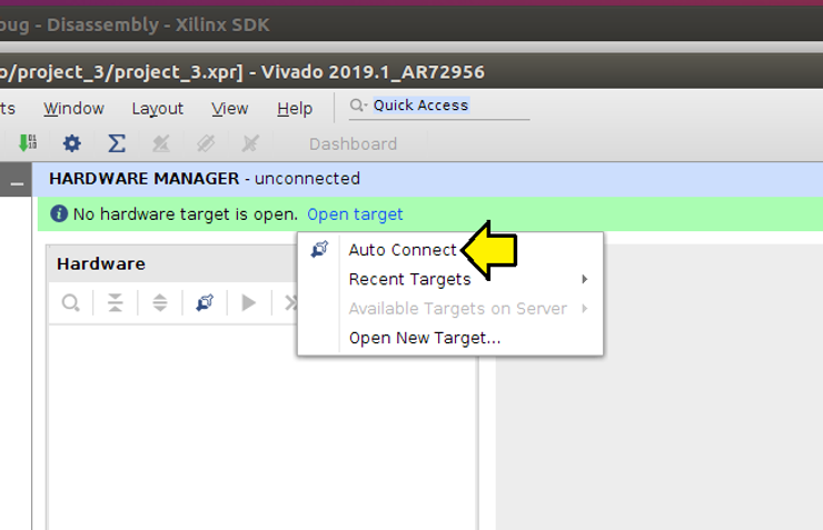
Step #7: Click Auto Connect
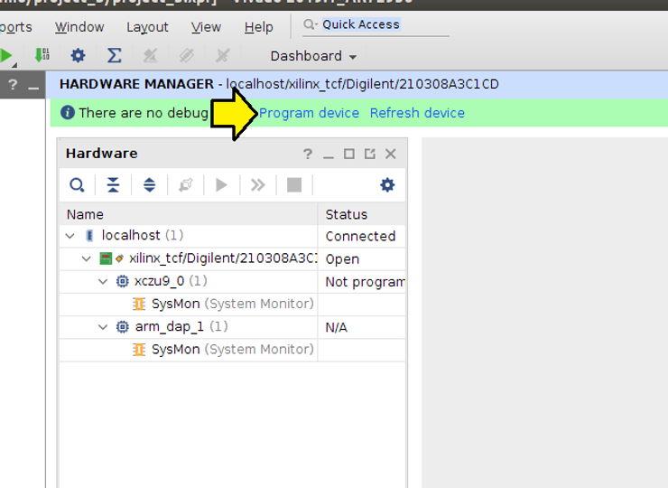
Step #8: Click Program device
Step #9: Click Program
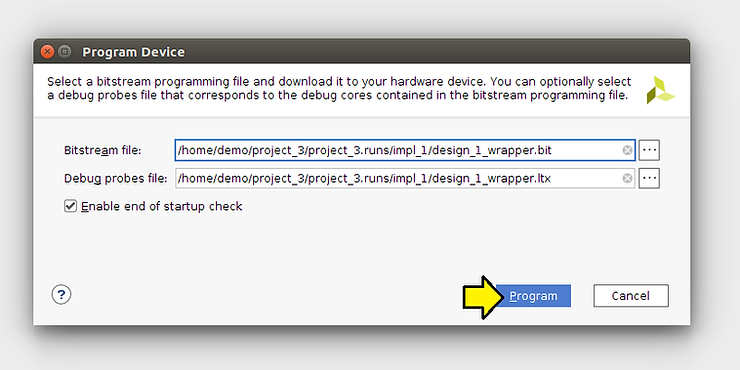
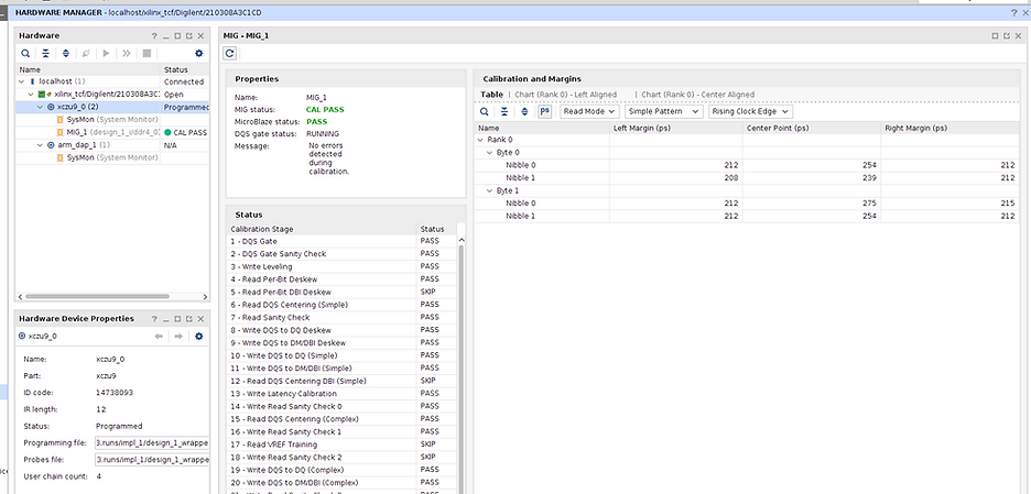
You should see:
Export the Design for UART Smoke Test with XSDK and Creating a Linux Build with PetaLinux
Steps
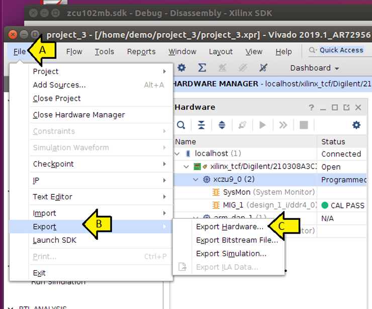
Step #1: (A) Click File, (B) Export, and (C) Export Hardware…
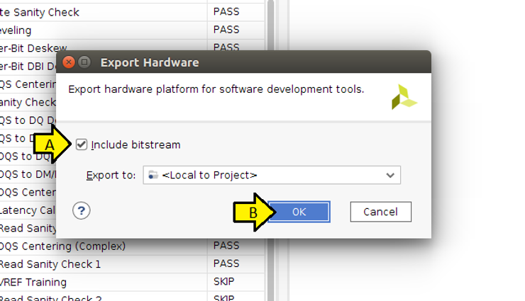
Step #1.1: Click OK
Create a Hello World test App to Test the UART Works Before Creating a Linux Build
Steps
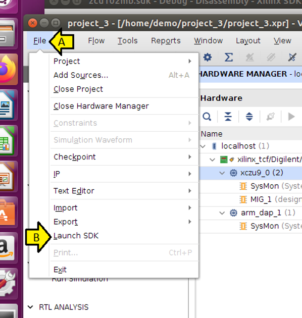
Step #1: (A) Click File and (B) click Launch SDK
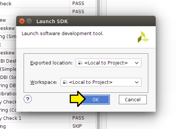
Step #1.1: Click OK
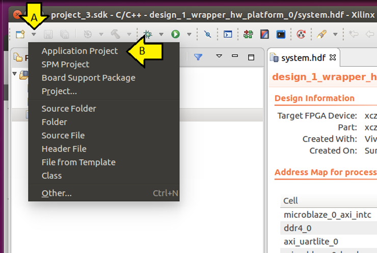
Step #2: (A) Click the drop-down and (B) click Application Project
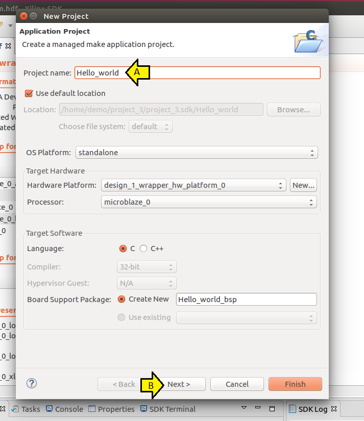
Step #2.1: (A) Use Hello_world for the Project name: and (B) click Next
Important Note: never use spaces; the SDK cannot handle spaces
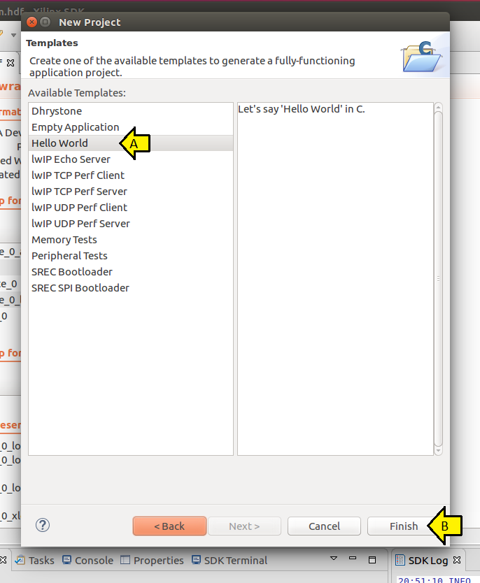
Step #2.2: (A) Click Hello World and (B) Finish
Step #3: Open a terminal and start screen using:
screen /dev/ttyUSB2 9600
Note 1: Type Ctrl-a d to detach, Ctrl-a k to kill
Note 2: After detaching, reattached with:
screen -r
Note 3: if someone else has attached, reattach with:
screen -x
Note 4: to clear what’s in a screen, type Ctrl-a C. To get more commands, type Ctrl-a ?
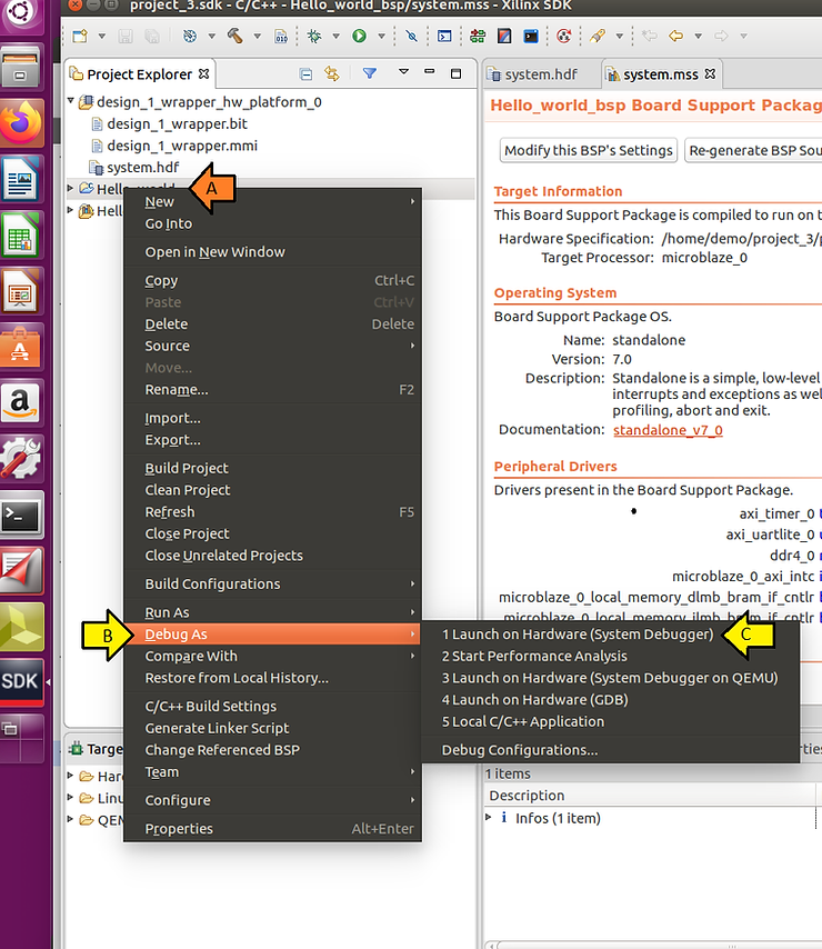
Step #4: (A) Right-click on Hello_world, (B) click Debug As, and (C) click Launch on Hardware (System Debugger)
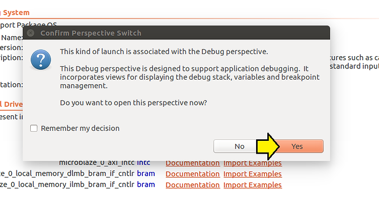
Step #5: Click Yes to Confirm Perspective Switch
You will likely not see anything because the target is stuck at:
void XUartLite_SendByte(UINTPTR BaseAddress, u8 Data)
{
 while (XUartLite_IsTransmitFull(BaseAddress));   /* <<<<< stuck */

 XUartLite_WriteReg(BaseAddress, XUL_TX_FIFO_OFFSET, Data);
}
…and the memory load from the UART returned:
xsct% mrd 0x40600000
xsct% Memory read error at 0x40600000. Memory access exception
0xdec0ce1c
We’ll fix that next by ensuring we click the Reset entire system check box in the Debug configuration.
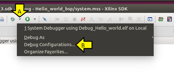
Step #6: (A) Click the debug drop down and (B) click Debug Configurations….
Step #6.1: (A) Check the Reset entire system checkbox, (B) click Apply, and (C) click Debug
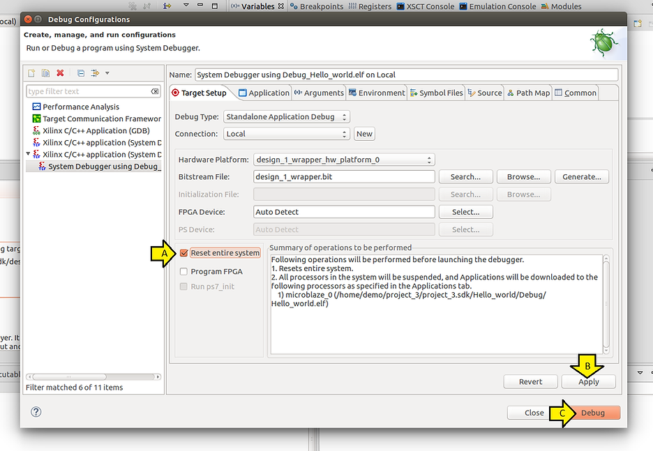
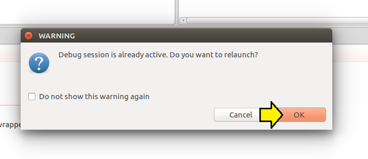
Step #6.2: Click OK
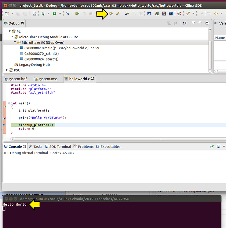
Step #7:Click Step Over
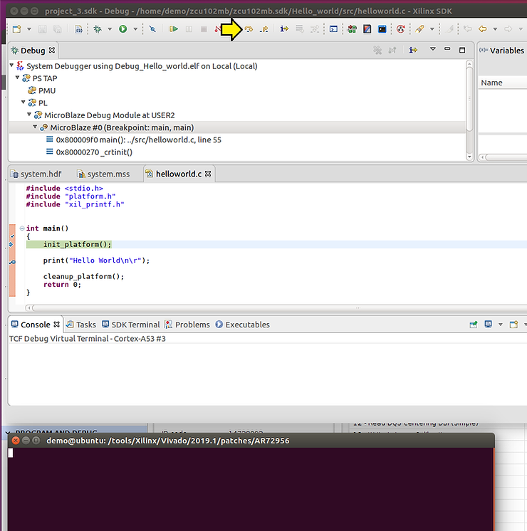
Step #7.1: Click Step Over again
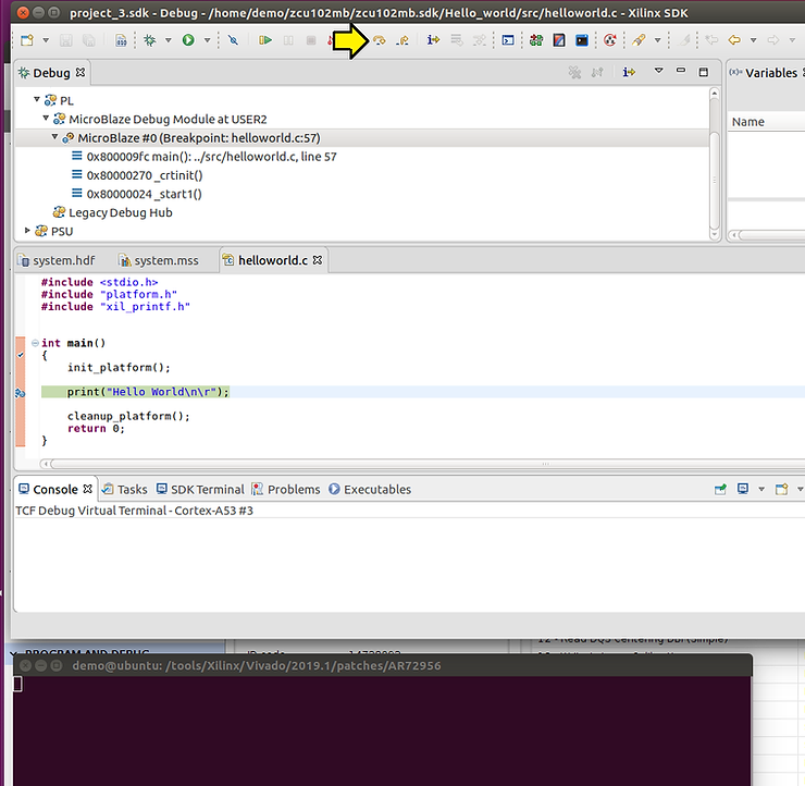
Step #7.2: …and one more time observing Hello World on your screen session
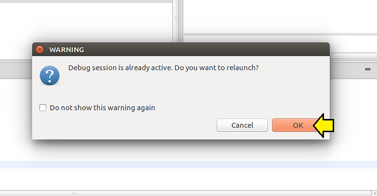
Note: To restart debugging, click the Bug…
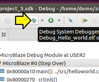
…and click OK…
Create and Build MicroBlaze Linux
Steps
Step #1: Type the following to create a PetaLinux project and build it
cd plxprjs/
source ~/petalinux/2019.1/settings.sh
petalinux-create --type project --template microblaze --name zcu102mb
cd zcu102mb
petalinux-config --get-hw-description=/home/demo/project_3/project_3.sdk
# Accept defaults and exit (just select Exit in the autoconfig)
petalinux-build
Step #2: Reset the ZCU102
Step #3: Download the FPGA using xsct
cd /home/demo/petalinux/2019.1/tools/xsct/bin/
 ./xsct
 connect -url tcp:localhost:3121
 targets
 # Select the PL
 targets 3
 fpga -no-revision-check /home/demo/plxprjs/zcu102mb/images/linux/system.bit
Note 1:
I needed to use xsct flow because I got a
WARNING: [Xicom 50-99] Incorrect bitstream assigned to device. Bitstream was generated for part xczu9eg-ffvb1156-2-e, target device (with IDCODE revision 1) is compatible with es2 revision bitstreams.
Note 2: You can download the bit file using HARDWARE MANAGER by running:
set_param xicom.use_bitstream_version_check false
…in Vivado
Step #4: Back in PetaLinux type:
petalinux-boot --jtag --kernel -v
Note: Consider always using -v to see what the command actually does
Step #5: Examine build output:
INFO: sourcing build tools
XSDB Script:
INFO: Launching XSDB for file download and boot.
INFO: This may take a few minutes, depending on the size of your image.

connect
targets -set -nocase -filter {name =~ "microblaze*#0"}
puts stderr "INFO: Downloading ELF file: /home/demo/plxprjs/zcu102mb/images/linux/image.elf to the target."
dow "/home/demo/plxprjs/zcu102mb/images/linux/image.elf"
after 2000
con
exit
rlwrap: warning: your $TERM is 'xterm-256color' but rlwrap couldn't find it in the terminfo database. Expect some problems.: Inappropriate ioctl for device
INFO: Downloading ELF file: /home/demo/plxprjs/zcu102mb/images/linux/image.elf to the target.
Downloading Program -- /home/demo/plxprjs/zcu102mb/images/linux/image.elf
 section, .text: 0xc0000000 - 0xc043d427
 section, __fdt_blob: 0xc043d428 - 0xc044d427
 section, .rodata: 0xc044e000 - 0xc0565adf
 section, .pci_fixup: 0xc0565ae0 - 0xc056767f
 section, __ksymtab: 0xc0567680 - 0xc056ddbf
 section, __ksymtab_gpl: 0xc056ddc0 - 0xc0572717
 section, __ksymtab_strings: 0xc0572718 - 0xc058bf6c
 section, __param: 0xc058bf70 - 0xc058c537
 section, __modver: 0xc058c538 - 0xc058cfff
 section, __ex_table: 0xc058d000 - 0xc058e53f
 section, .notes: 0xc058e540 - 0xc058e57b
 section, .sdata2: 0xc058e57c - 0xc058efff
 section, .data: 0xc058f000 - 0xc05b557f
 section, .init.text: 0xc05b6000 - 0xc05d9c1f
 section, .init.data: 0xc05d9c20 - 0xc05db6b3
 section, .init.ivt: 0xc05db6b4 - 0xc05db6db
 section, .init.setup: 0xc05db6dc - 0xc05dba8f
 section, .initcall.init: 0xc05dba90 - 0xc05dbe07
 section, .con_initcall.init: 0xc05dbe08 - 0xc05dbe0b
 section, .init.ramfs: 0xc05dbe0c - 0xc1283013
 section, .bss: 0xc1284000 - 0xc1310533
100% 18MB 0.2MB/s 01:52
Setting PC to Program Start Address 0x80000000
Successfully downloaded /home/demo/plxprjs/zcu102mb/images/linux/image.elf
Step #6: Examine console output
Note 1: it looks like the console hangs, but it eventually came up (after a few minutes)
Note 2: Use root for the username and root for the password
Ramdisk addr 0x00000000,
Compiled-in FDT at (ptrval)
Linux version 4.19.0-xilinx-v2019.1 (oe-user@oe-host) (gcc version 8.2.0 (GCC)) #1 Sun Mar 7 18:29:2
2 UTC 2021
setup_memory: max_mapnr: 0x20000
setup_memory: min_low_pfn: 0x80000
setup_memory: max_low_pfn: 0xa0000
setup_memory: max_pfn: 0xa0000
Zone ranges:
 DMA [mem 0x0000000080000000-0x000000009fffffff]
 Normal empty
 HighMem empty
Movable zone start for each node
Early memory node ranges
 node 0: [mem 0x0000000080000000-0x000000009fffffff]
Initmem setup node 0 [mem 0x0000000080000000-0x000000009fffffff]
On node 0 totalpages: 131072
 DMA zone: 1024 pages used for memmap
 DMA zone: 0 pages reserved
 DMA zone: 131072 pages, LIFO batch:31
setup_cpuinfo: initialising
setup_cpuinfo: Using full CPU PVR support
wt_msr_noirq
pcpu-alloc: s0 r0 d32768 u32768 alloc=1*32768
pcpu-alloc: [0] 0
Built 1 zonelists, mobility grouping on. Total pages: 130048
Kernel command line: console=ttyUL0,9600 earlyprintk
Dentry cache hash table entries: 65536 (order: 6, 262144 bytes)
Inode-cache hash table entries: 32768 (order: 5, 131072 bytes)
Memory: 499716K/524288K available (4341K kernel code, 153K rwdata, 1276K rodata, 13108K init, 561K b
ss, 24572K reserved, 0K cma-reserved, 0K highmem)
Kernel virtual memory layout:
 * 0xfffea000..0xfffff000 : fixmap
 * 0xff800000..0xffc00000 : highmem PTEs
 * 0xff800000..0xff800000 : early ioremap
 * 0xf0000000..0xff800000 : vmalloc & ioremap
NR_IRQS: 64, nr_irqs: 64, preallocated irqs: 0
irq-xilinx: /amba_pl/interrupt-controller@41200000: num_irq=2, edge=0x1
/amba_pl/timer@41c00000: irq=1
clocksource: xilinx_clocksource: mask: 0xffffffff max_cycles: 0xffffffff, max_idle_ns: 6370868154 ns
xilinx_timer_shutdown
xilinx_timer_set_periodic
sched_clock: 32 bits at 300MHz, resolution 3ns, wraps every 7158278654ns
Calibrating delay loop... 49.35 BogoMIPS (lpj=246784)
pid_max: default: 4096 minimum: 301
Mount-cache hash table entries: 1024 (order: 0, 4096 bytes)
Mountpoint-cache hash table entries: 1024 (order: 0, 4096 bytes)
devtmpfs: initialized
random: get_random_u32 called from bucket_table_alloc+0xa0/0x23c with crng_init=0
clocksource: jiffies: mask: 0xffffffff max_cycles: 0xffffffff, max_idle_ns: 19112604462750000 ns
futex hash table entries: 16 (order: -4, 448 bytes)
NET: Registered protocol family 16
audit: initializing netlink subsys (disabled)
PCI: Probing PCI hardware
audit: type=2000 audit(0.200:1): state=initialized audit_enabled=0 res=1
vgaarb: loaded
clocksource: Switched to clocksource xilinx_clocksource
NET: Registered protocol family 2
tcp_listen_portaddr_hash hash table entries: 256 (order: 0, 6144 bytes)
TCP established hash table entries: 4096 (order: 2, 16384 bytes)
TCP bind hash table entries: 4096 (order: 4, 81920 bytes)
TCP: Hash tables configured (established 4096 bind 4096)
UDP hash table entries: 256 (order: 1, 12288 bytes)
UDP-Lite hash table entries: 256 (order: 1, 12288 bytes)
NET: Registered protocol family 1
RPC: Registered named UNIX socket transport module.
RPC: Registered udp transport module.
RPC: Registered tcp transport module.
RPC: Registered tcp NFSv4.1 backchannel transport module.
PCI: CLS 0 bytes, default 32
random: fast init done
Skipping unavailable RESET gpio -2 (reset)
workingset: timestamp_bits=30 max_order=17 bucket_order=0
romfs: ROMFS MTD (C) 2007 Red Hat, Inc.
io scheduler noop registered
io scheduler deadline registered
io scheduler cfq registered (default)
io scheduler mq-deadline registered
io scheduler kyber registered
Serial: 8250/16550 driver, 4 ports, IRQ sharing disabled
40600000.serial: ttyUL0 at MMIO 0x40600000 (irq = 2, base_baud = 0) is a uartlite
console [ttyUL0] enabled
brd: module loaded
libphy: Fixed MDIO Bus: probed
NET: Registered protocol family 17
Key type encrypted registered
Warning: unable to open an initial console.
Freeing unused kernel memory: 13108K
This architecture does not have kernel memory protection.
Run /init as init process
random: dd: uninitialized urandom read (512 bytes read)
random: dropbearkey: uninitialized urandom read (32 bytes read)
random: dropbearkey: uninitialized urandom read (32 bytes read)
random: crng init done

PetaLinux 2019.1 zcu102mb /dev/ttyUL0

zcu102mb login:
Example of Checking the Pins and How the Pins Map to a Part
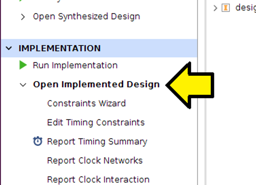
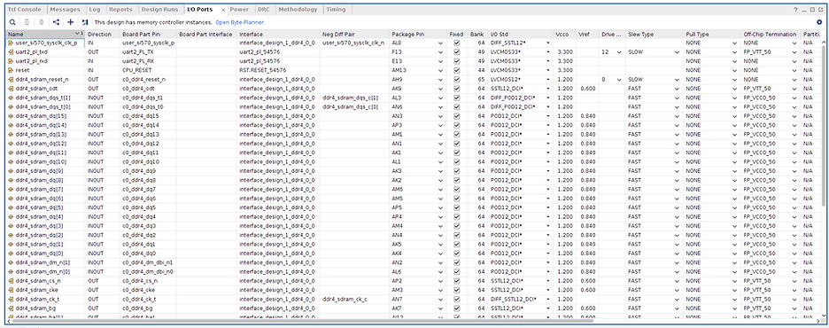
Once the bitstream has completed, check package pins
To get to the Package Pins
Step #1: Click Open Implemented Design
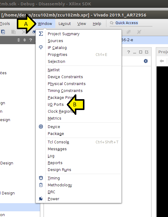
Step #2: A) Click Window, B) click I/O Ports
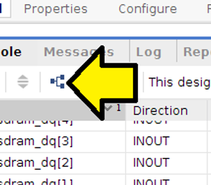
Step #3: Turn off Group by Interface and Bus to get a linear tale
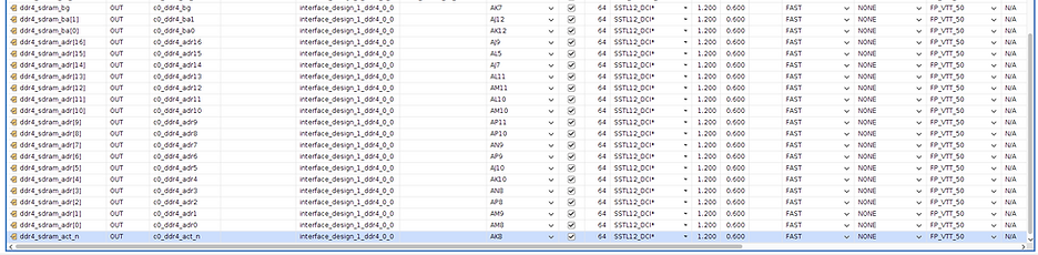
Package Pins:
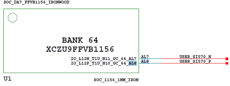
USER_SI570
Schematic
AL7 USER_SI570_N
AL8 USER_SI570_P
SI570
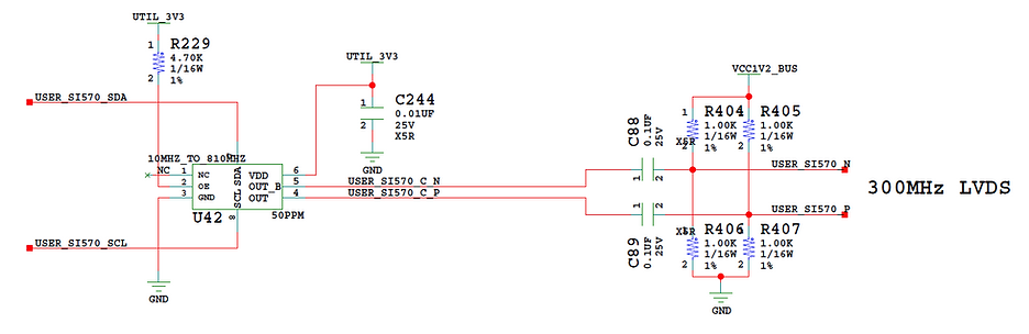
BOM
Ref Des: U42
Device: Oscillator
Package: SI570
Value: 10MHZ_TO_810MHZ
Voltage: N/A
Tolerance: 50PPM
Dielectric: N/A
Power: N/A
Manf: SILABS
Manf P/N: 570BAB001614DG
Dist: Silicon Labs
Dist P/N: 570BAB001614DG
Alternate P/N: N/A
Barcode: 600047
Datasheet
https://www.silabs.com/documents/public/data-sheets/si570.pdf
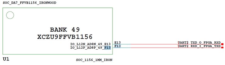
UART2_TXD_O_FPGA_RXD & UART2_RXD_I_FPGA_TXD
Schematic
F13 UART2_TXD_O_FPGA_RXD
E13 UART2_RXD_I_FPGA_TXD
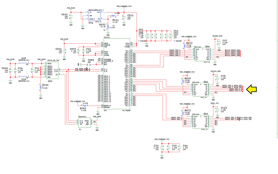
BOM
CP2108
Item#: 268
Qty: 1
Ref Des: U40
Device: IC Bridge
Package: 64_VFQFN
Value: CP2108
Voltage: 3.3V
Tolerance: N/A
Dielectric: N/A
Power: N/A
Manf: SILICON LABS
Manf P/N: CP2108-B02-GM
Dist: Digikey
Dist P/N: 336-3020-ND
Alternate P/N: N/A
Barcode: 500404
Datasheet
https://www.silabs.com/documents/public/data-sheets/cp2108-datasheet.pdf
Core Docs
mdm_0
MicroBlaze Debug Module (MDM) (3.2)
MicroBlaze Debug Module v3.2 LogiCORE IP Product Guide Vivado Design Suite
PG115 (v3.2) January 21, 2021
https://www.xilinx.com/support/documentation/ip_documentation/mdm/v3_2/pg115-mdm.pdf
ddr4_0
DDR4 SDRAM (MIG) (2.2)
https://www.xilinx.com/support/documentation/ip_documentation/ultrascale_memory_ip/v1_4/pg150-ultrascale-memory-ip.pdf
microblaze_0
MicroBlaze (11.0)
https://www.xilinx.com/support/documentation/sw_manuals/xilinx2019_1/ug984-vivado-microblaze-ref.pdf
rst_ddr4_0_300M
Processor System Reset (5.0)
Processor System Reset Module v5.0 LogiCORE IP Product Guide PG164 November 18, 2015
https://www.xilinx.com/support/documentation/ip_documentation/proc_sys_reset/v5_0/pg164-proc-sys-reset.pdf
axi_uartlite_0
AXI Uartlite (2.0)
AXI UART Lite v2.0 LogiCORE IP Product Guide Vivado Design Suite PG142 April 5, 2017
https://www.xilinx.com/support/documentation/ip_documentation/axi_uartlite/v2_0/pg142-axi-uartlite.pdf
axi_smc
AXI SmartConnect (1.0)
SmartConnect v1.0 LogiCORE IP Product Guide Vivado Design Suite PG247 February 3, 2020
https://www.xilinx.com/support/documentation/ip_documentation/smartconnect/v1_0/pg247-smartconnect.pdf
rst_ddr4_0_100M
Processor System Reset
Processor System Reset (5.0)
Processor System Reset Module v5.0 LogiCORE IP Product Guide PG164 November 18, 2015
https://www.xilinx.com/support/documentation/ip_documentation/proc_sys_reset/v5_0/pg164-proc-sys-reset.pdf
microblaze_0_axi_periph
AXI Interconnect
AXI Interconnect (2.1)
AXI Interconnect v2.1 LogiCORE IP Product Guide Vivado Design Suite PG059 December 20, 2017
https://www.xilinx.com/support/documentation/ip_documentation/axi_interconnect/v2_1/pg059-axi-interconnect.pdf
microblaze_0_xlconcat
Concat
Concat (2.1)
microblaze_0_axi_intc
AXI Interrupt Controller
AXI Interrupt Controller (4.1)
AXI Interrupt Controller (INTC) v4.1 LogiCORE IP Product Guide Vivado Design Suite PG099 June 24, 2020
https://www.xilinx.com/support/documentation/ip_documentation/axi_intc/v4_1/pg099-axi-intc.pdf
microblaze_0_local_memory
dlmb_v10
Local Memory Bus (LMB) 1.0
Local Memory Bus (LMB) v3.0 LogiCORE IP Product Guide Vivado Design Suite PG113 April 6, 2016
https://www.xilinx.com/support/documentation/ip_documentation/lmb_v10/v3_0/pg113-lmb-v10.pdf
dlmb_bram_if_cntlr
LMB BRAM Controller
LMB BRAM Controller (4.0)
LMB BRAM Interface Controller v4.0 LogiCORE IP Product Guide Vivado Design Suite PG112 January 21, 2021
https://www.xilinx.com/support/documentation/ip_documentation/lmb_bram_if_cntlr/v4_0/pg112-lmb-bram-if-cntlr.pdf
lmb_bram
Block Memory Generator
Block Memory Generator (8.4)
Block Memory Generator v8.4 LogiCORE IP Product Guide Vivado Design Suite PG058 December 9, 2019
https://www.xilinx.com/support/documentation/ip_documentation/blk_mem_gen/v8_4/pg058-blk-mem-gen.pdf
References
Zynq UltraScale+ MPSoC ZCU102 Evaluation Kit
https://www.xilinx.com/products/boards-and-kits/ek-u1-zcu102-g.html
PetaLinux Tools Documentation Reference Guide UG1144 (v2019.1) May 22, 2019
https://www.xilinx.com/support/documentation/sw_manuals/xilinx2019_1/ug1144-petalinux-tools-reference-guide.pdf
MicroBlaze Processor Reference Guide UG984 (v2019.1) May 22, 2019:
https://www.xilinx.com/support/documentation/sw_manuals/xilinx2019_1/ug984-vivado-microblaze-ref.pdf
MicroZed Chronicles: Building PetaLinux for MicroBlaze — Part One
https://www.hackster.io/news/microzed-chronicles-building-petalinux-for-microblaze-part-one-6258b21fbd51
MicroZed Chronicles: Building PetaLinux for MicroBlaze — Part 2
https://www.hackster.io/news/microzed-chronicles-building-petalinux-for-microblaze-part-2-ced17ae4ca67
Running Hello World on Microblaze + ZCU102
https://www.youtube.com/watch?v=66kYoCOoIc4
Utilizing PS memory to execute Microblaze application on Zynq Ultrascale
https://xilinx-wiki.atlassian.net/wiki/spaces/A/pages/18841793/Utilizing+PS+memory+to+execute+Microblaze+application+on+Zynq+Ultrascale
Vivado Design Suite User Guide Embedded Processor Hardware Design UG898 (v2019.1) June 4, 2019
https://www.xilinx.com/support/documentation/sw_manuals/xilinx2019_1/ug898-vivado-embedded-design.pdf
Vivado Design Suite User Guide Designing IP Subsystems Using IP Integrator UG994 (v2019.1) May 22, 2019
https://www.xilinx.com/support/documentation/sw_manuals/xilinx2019_1/ug994-vivado-ip-subsystems.pdf
Generating Basic Software Platforms Reference Guide
UG1138 (v2018.2) July 16, 2018
UG1138 (v2019.2) October 30, 2019
https://www.xilinx.com/content/dam/xilinx/support/documentation/sw_manuals/xilinx2020_1/ug1138-generating-basic-software-platforms.pdf
Xilinx logo from [link]