
Detailed Info on How to Use a Hewlett-Packard 3312A Function Generator:
This post helps a user go through the basic functions of the Hewlett-Packard HP 3312A Function Generator. Based on feedback and surveys, this post will be updated to include more complex functions and questions about how to use this device for an activity.
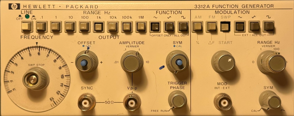
Important Reference Links:
If there are any questions, please refer to the following sources.
https://www.youtube.com/@centennialsof https://xdevs.com/doc/HP_Agilent_Keysight/HP%203312A%20Operation%20Only.pdf
Equipment
The equipment below is required for use and testing on circuits. With function generators, especially older models like this one, it is highly recommended to use an oscilloscope to verify your measurements and outputs, unless you plan to test continuously to maintain consistent accuracy over a prolonged period of time. The equipment below is all that you will ever need for a function generator to use with a circuit, but it is much more than what you need to test a function generator.
50 ohm feedthrough adapter
2-3 BNC cables
BNC tee adapter
BNC Test adapter
Known working multimeter
Known working oscilloscope
Powering On
When powering on the machine, you must be very mindful of the power being received by the device. This device does not have an automatic power regulator like most devices today and must be manually adjusted to match your outlet.
First, use a known-good multimeter to measure the voltage of your power outlet. Second, on the back of the HP 3312A, there are two switches. The first one is for smaller voltages, 100V and 120V. The second one has large ones of 240V and 220V. The first switch, as shown below, has two settings. and must be manually adjusted to match your outlet.
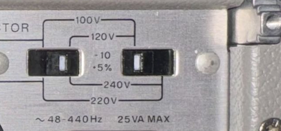
Switch the first switch to the left when your voltage is closer to 100 volts or 220 volts, and to the right when your voltage is closer to 120 volts or 240 volts. The second switch determines the higher or lower setting. Switch the second switch to the left when your voltage is closer to 100 or 120 volts, and to the right when your voltage is closer to 220 or 240 volts. If your voltage falls between these values, round to the nearest value.
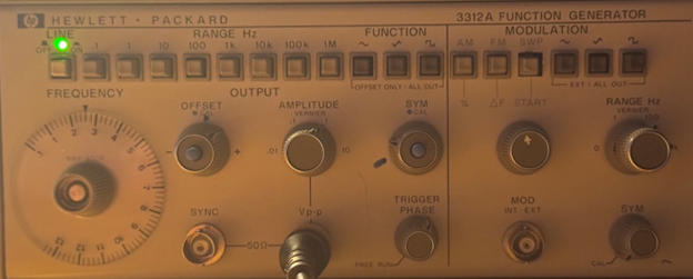
After setting the device to the proper voltage regulation, set all knobs to the positions shown below, with all blue buttons set in the out position. This ensures that when testing the generator, you can see how each button works as the default.
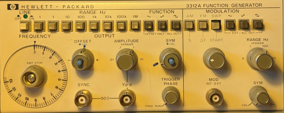
This function generator has markings to show the default position of that function. For this tutorial, I am also using a DSOX1102G Keysight digital oscilloscope. Please refer to the testing section for more information on how to calibrate your generator.
Functions
This function generator has three main functions that form the basis of all outputted waves. The first universal step is to connect your function generator to a known-working oscilloscope with a BNC cable and a 50 ohm feedthrough adapter. The 50 ohm adapter should be connected to the oscilloscope, and not the function generator. This adapter helps with monitoring output, and even though it is not always necessary with newer models, older models usually need the converter. If your oscilloscope has a receiving impedance of 1 M, you will need this adapter.
When setting the frequency, this tutorial will refer to the frequency dial as FREQUENCY and the buttons above the dial as RANGE HZ. Both of these settings are needed to set the frequency. The buttons at the top set the range of frequency, as listed, and the frequency dial sets the exact number within that range. For instance, pressing the RANGE HZ button of 1k sets the function generator frequency range to 1000 Hz. The dial can then set the frequency between the range of 100 Hz and 13000 Hz.
Square Waves
Start with a square wave because this will help calibrate and visualize wave inaccuracies.
AC coupling for Square Waves
1.) Set the coupling to AC on the oscilloscope
2.) Press the square function button
3.) Press the 10 Range Hz button
4.) Set AMPLITUDE to 1
5.) Keep the TRIGGER PHASE to free run
6.) Set FREQUENCY from 1-6
7.) Use the horizontal knob to adjust the visual to about 200 mV/div
8.) Use the vertical knob to adjust the visual to about 5 ms/div
If you see sloping such as this:
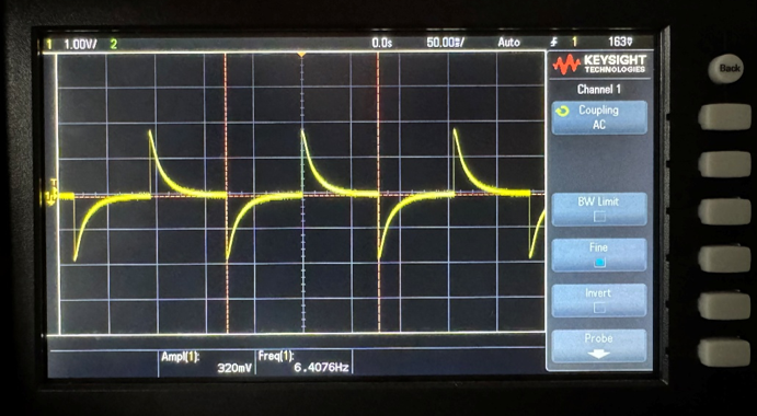
This is great! The wave should look like this on an unscaled AC coupling output. To have a better view, simply switch the coupling to DC. It should now look like this:
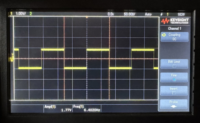
DC output should be used for frequencies ≥100 Hz, while AC output should be used for frequencies ≤100 Hz.
DC Coupling for Square Waves
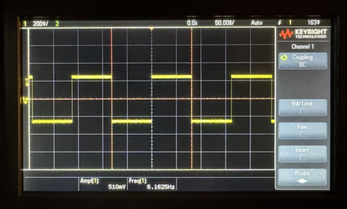
Next, once DC coupling is set, change the following buttons to the corresponding values for expected displays and range accuracy. The following examples have a set frequency of 6. See Button Functions in the Appendix for more information on Range and Frequency.
Press 1 range Hz, oscilloscope vertical set to 200 mV/div and horizontal to 50 ms/div:
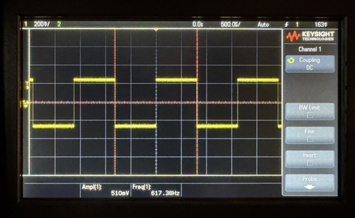
Press 100 range Hz, oscilloscope vertical set to 200 mV/div and horizontal to 500 µs/div:
Press 100k range Hz, oscilloscope vertical set to 200 mV/div and horizontal to 500 ns/div:
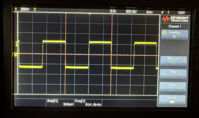
Press 100k range Hz, oscilloscope vertical set to 500 mV/div and horizontal to 500 ns/div, without the 50 ohm adapter:
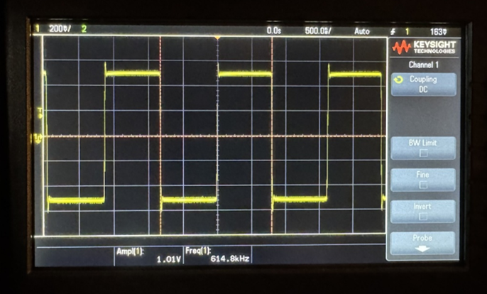
As you can see, the amplitude doubles, and due to the lack of dampening that the converter provides, a small tick in the wave is shown consistently.
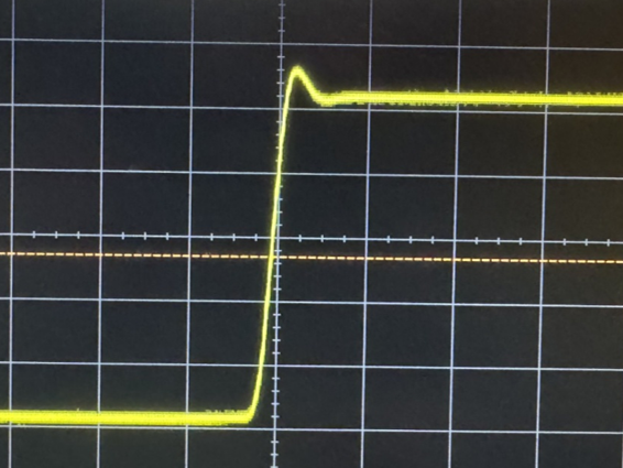
Here is a zoomed-in photo of that tick. This is unwanted, so having this adapter provides a nice cushion of wave accuracy, transferring a clean wave to the circuit.
Sine Waves
To set up a sine wave function on the function generator, the principles are similar, if not the same, as the square function.
AC Coupling for Sine Waves
1.) Set your coupling to AC on the oscilloscope
2.) Press the sine function button
3.) Press the 1 Range Hz button
4.) Set AMPLITUDE to 1
5.) Keep the TRIGGER PHASE to free run
6.) Set FREQUENCY from 1-6
7.) Use the horizontal knob to adjust the visual to about 300-1.5 V/div
8.) Use the vertical knob to adjust the visual to about 20-100 ms/div
For the following examples, the frequency is set to 6
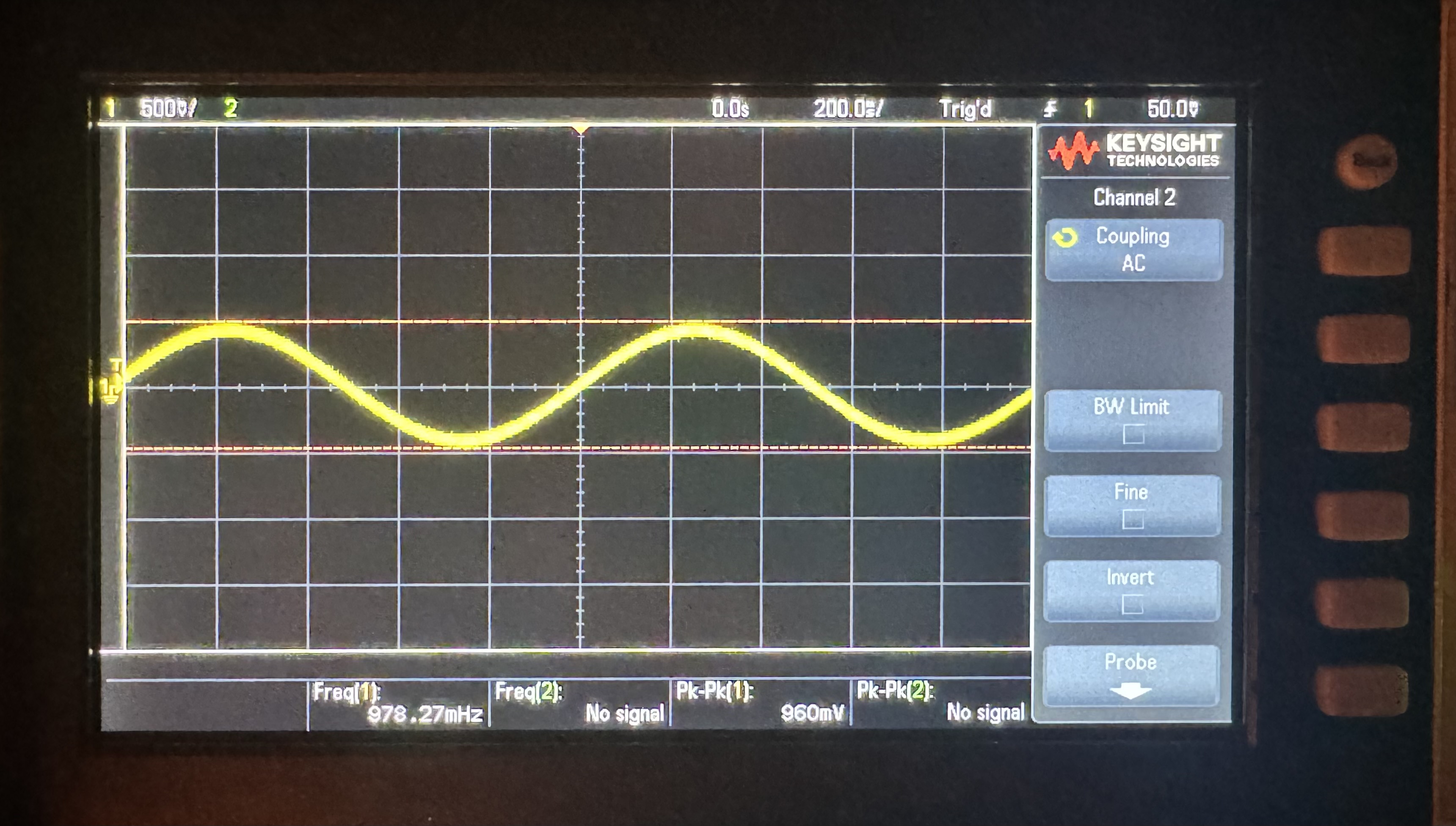
DC Coupling for Sine Waves
Press 1 range Hz, oscilloscope vertical set to 200 mV/div and horizontal to 50 ms/div:
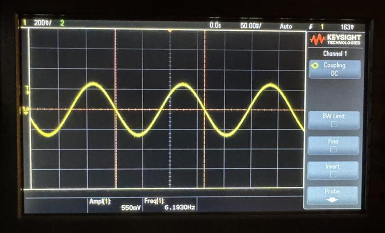
Press 100 range Hz, oscilloscope vertical set to 200 mV/div and horizontal to 500 µs/div:
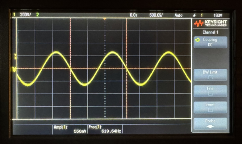
Press 100k range Hz, oscilloscope vertical set to 200 mV/div and horizontal to 500 ns/div:
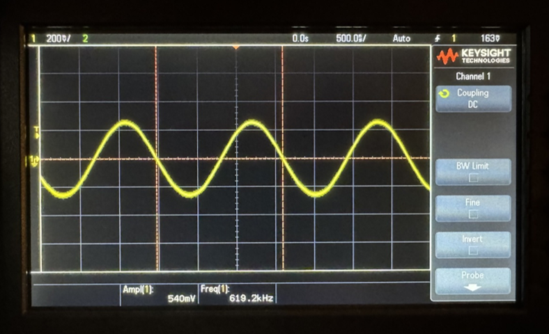
Press 100k range Hz, oscilloscope vertical set to 200 mV/div and horizontal to 500 ns/div, without the 50 ohm adapter:
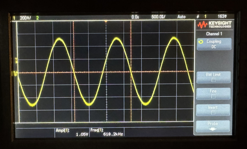
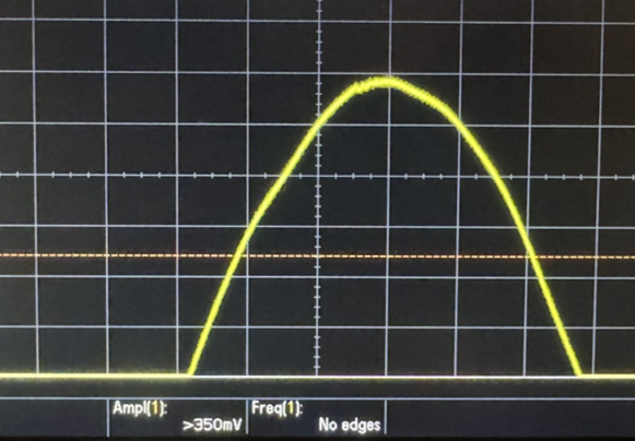
Zoomed in photo of tick, slight dip in sine wave, left wave peak leading into a “squiggle”.
Triangle Waves
To set up a triangle wave function on your oscilloscope, the principles are similar, if not the same, as the square function.
AC Coupling for Triangle Waves
1.) Set your coupling to AC on the oscilloscope
2.) Press the triangle function button
3.) Press the 1 Range Hz button
4.) Set the AMPLITUDE to 1
5.) Keep the TRIGGER PHASE to free run
6.) Set FREQUENCY from 1-6
7.) Use the horizontal knob to adjust the visual to about 300-1.5 V/div
8.) Use the vertical knob to adjust the visual to about 20-100 ms/div
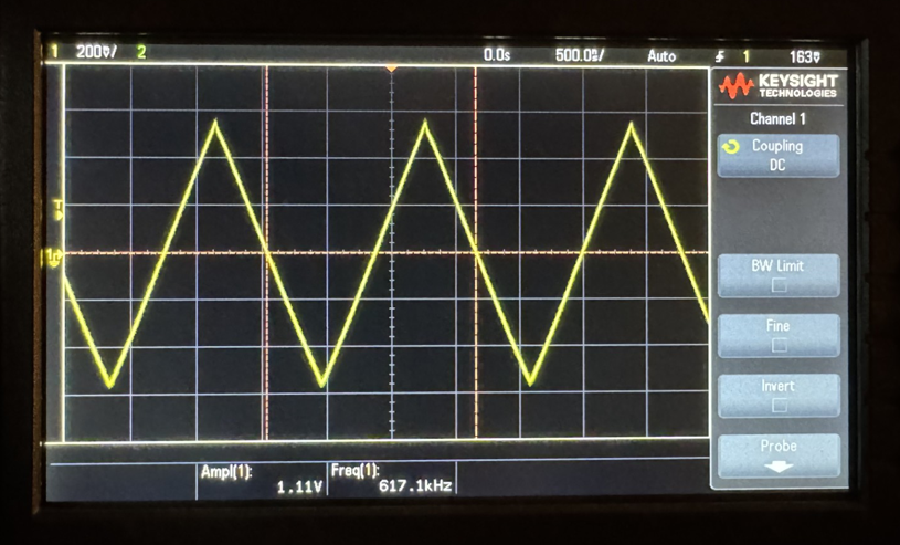
Set at a range of 1 Hz and a frequency of 6.
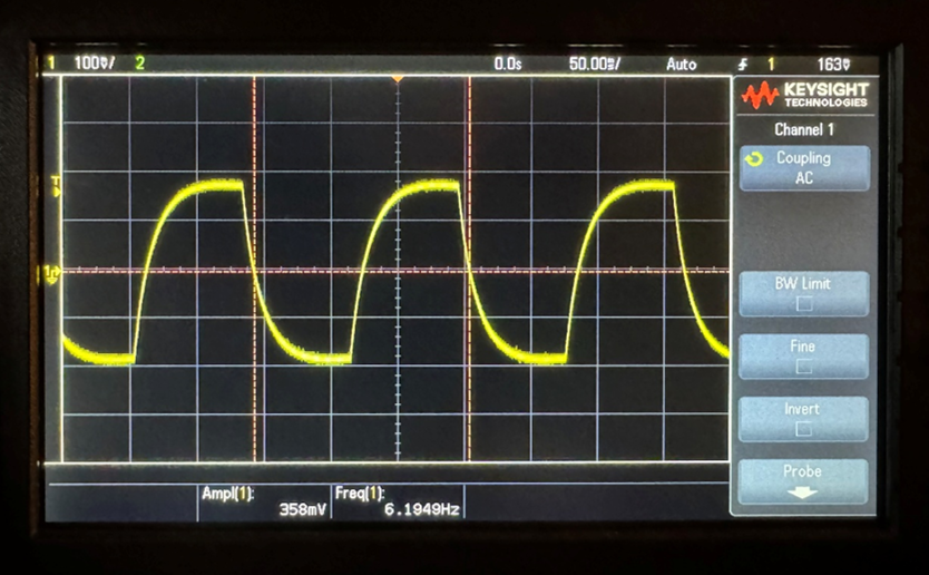
DC Coupling for Triangle Waves
Press 1 range Hz, oscilloscope vertical set to 200 mV/div and horizontal to 50 ms/div:
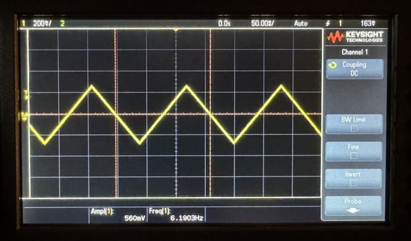
Press 100 range Hz, oscilloscope vertical set to 200 mV/div and horizontal to 500 µs/div:
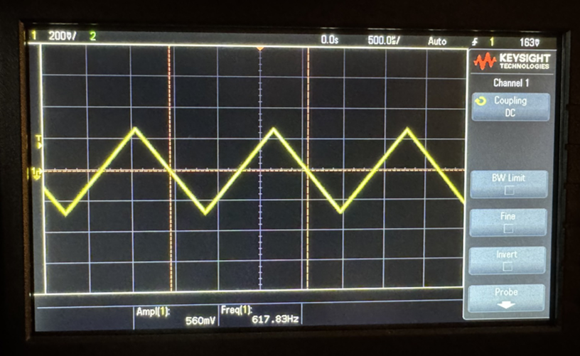
Press 100k range Hz, oscilloscope vertical set to 200 mV/div and horizontal to 500 ns/div:
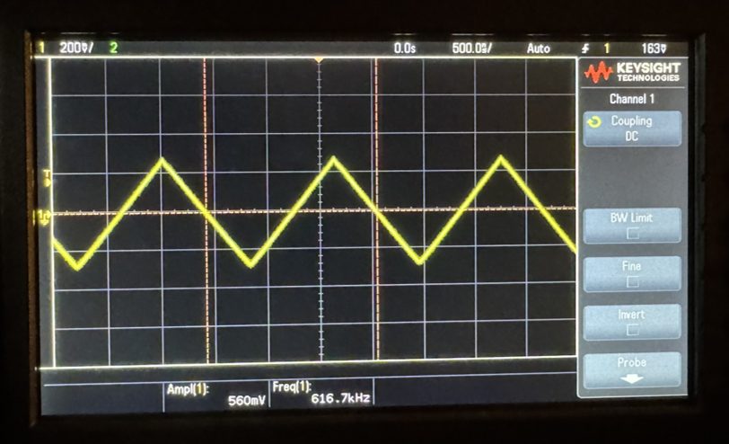
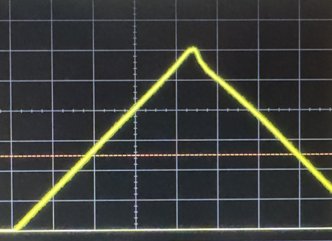
Press 100k range Hz, oscilloscope vertical set to 500 mV/div and horizontal to 500 ns/div, without the 50 ohm adapter:
Zoomed-in photo of a tick. Slightly dips on the right side of the wave.
Modulation
For modulation, the modulation output can be used to observe the modulation wave affecting the carrier wave. This can be helpful for physically seeing how the wave itself is affected.
The Range Hz knob adjusts the modulation function’s range, slowing or speeding up the modulation of the main function.
The Delta F START knob controls the amplitude of the modulation function, determining how far the function shifts in the Y direction for AM and in the X direction for FM and Sweep.
The SYM nob affects the symmetry of the modulation wave. Unlike the symmetry knob interaction with the regular functions, the SYM knob for modulation only affects the second half of the modulation, and cannot affect both directions.
AM
AM, or amplitude modulation, is a type of signal modulation primarily used in electronic communication, such as in radio and audio waves. AM works by modulating the carrier wave with a separate wave.
AM Sine:
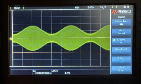
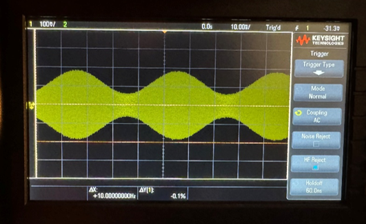
To use the AM function, start by selecting the sine function and sine modulation. Adjust Delta F START and range for desired results. SYM must be in the calibrated position. Zooming out to see the overall signal should show you the best representation of this modulation, and zooming in shows how the wave itself is affected.
Below are all possible combinations of functions with AM modulation. Compare with your own device.
Sine modulation – Sine Function:
Sine modulation – Triangle Function:
Sine modulation – Square Function:
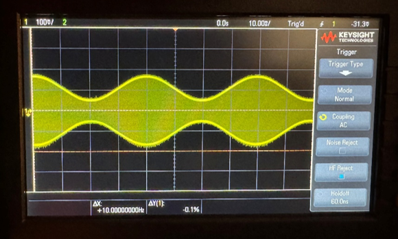
AM Triangle:
Triangle modulation – Sine Function:
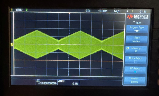
Triangle modulation – Triangle Function:
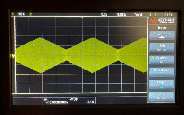
Triangle modulation – Square Function:
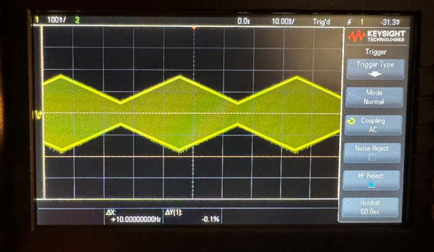
AM Square:
Square modulation – Sine Function:
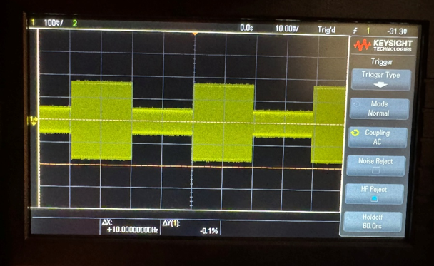
Square modulation – Triangle Function:
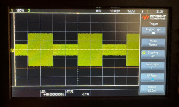
Square modulation – Square Function:
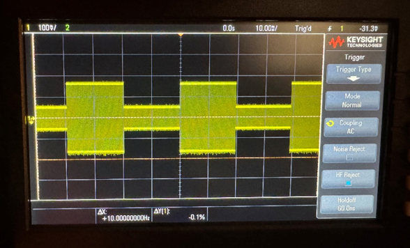
FM
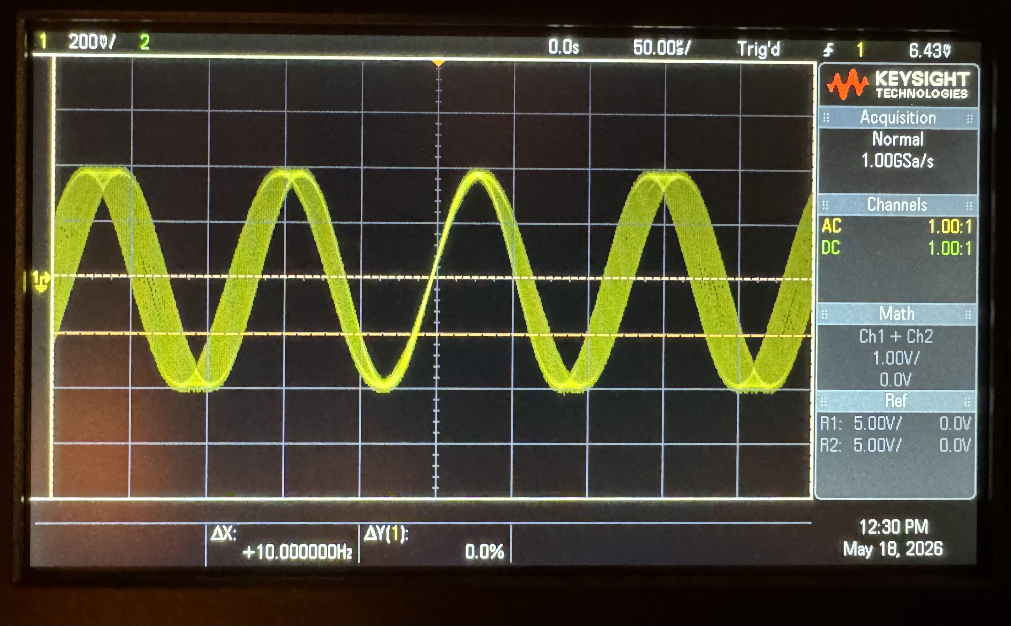
To use the FM modulation function, start by selecting the sine function and sine modulation. Adjust Delta F START and range for desired results. SYM modulation must be in the calibrated position. This modulation affects the horizontal components, so zooming out on a slower modulation will show a slight trend, although the proper way to view this modulation is at the normal viewing standard.
Compare each function modulation with your own device. Each Function is using sine modulation.
FM Sine:
FM Triangle:
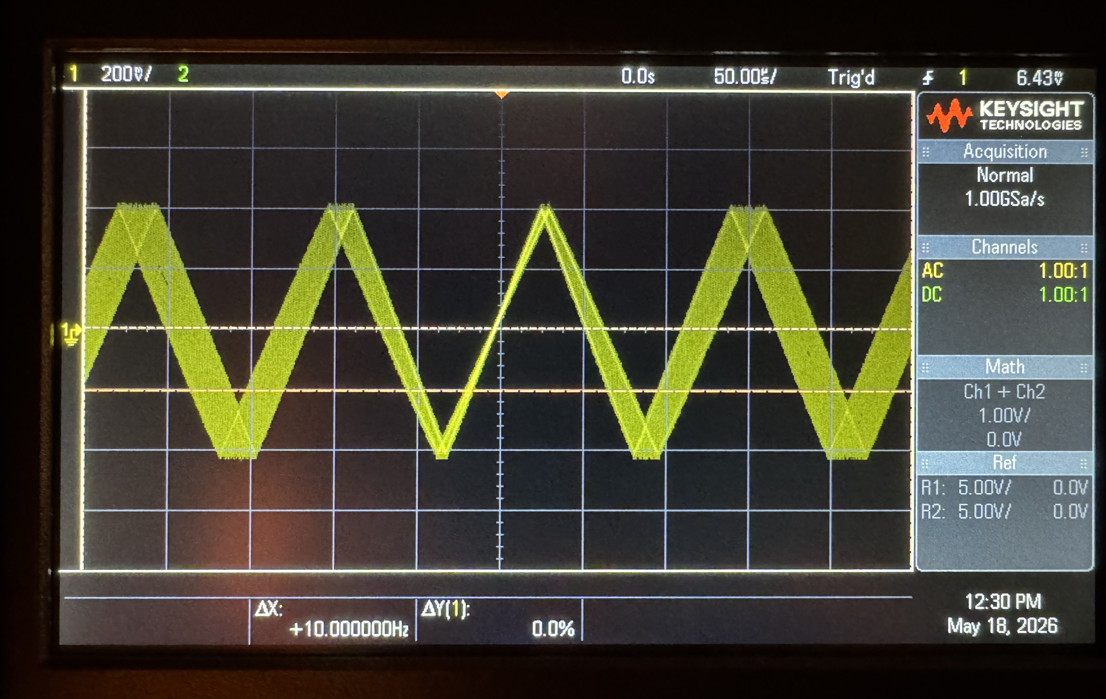
FM Square:
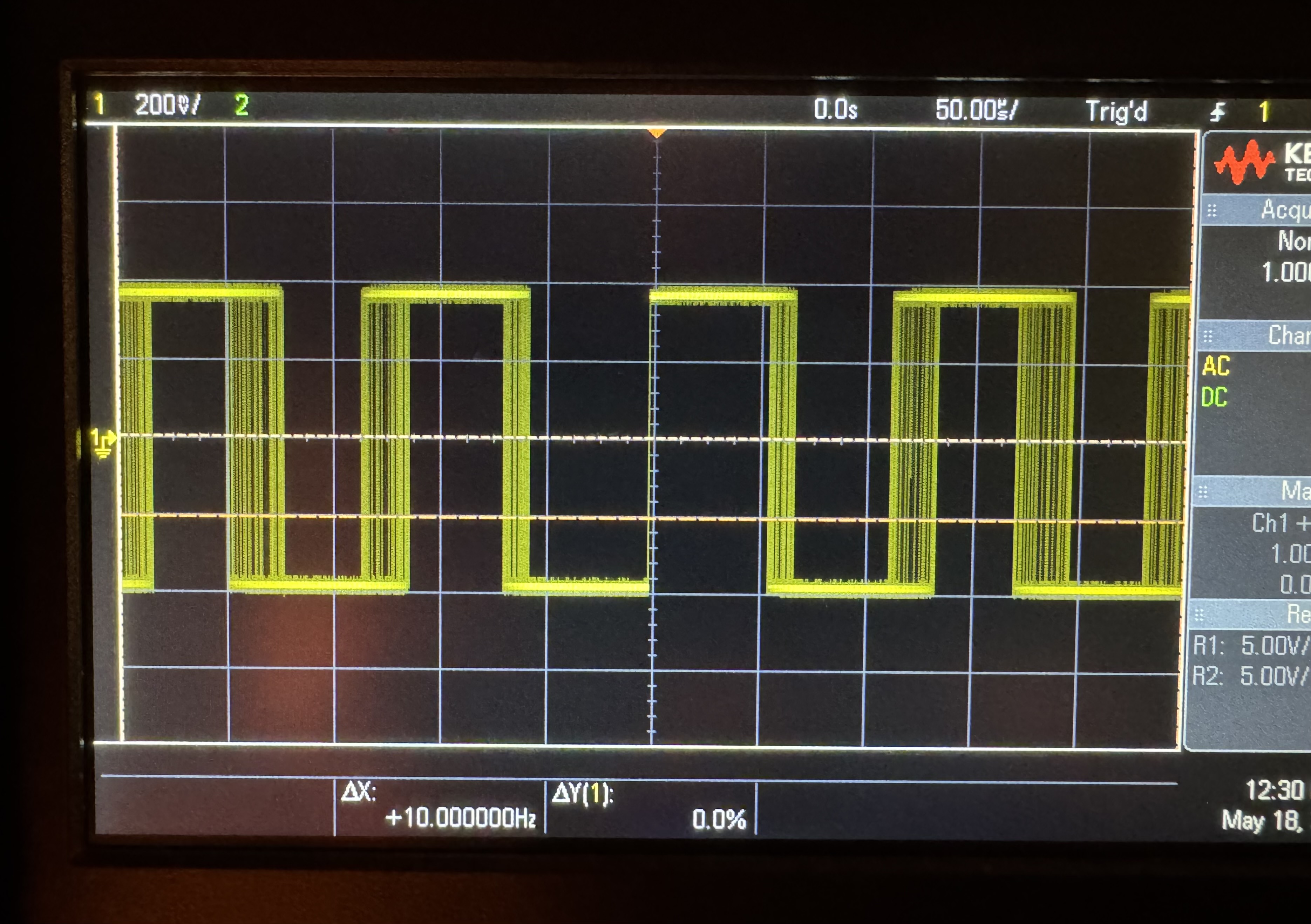
Sweep
The Sweep modulation function is mainly used for testing a circuit and its response to rapidly changing frequency over time. To use the Sweep modulation function, start by selecting just the sine function and making sure Delta F is set to its lowest point, or 0.
- Set the stop frequency with the FREQUENCY dial.
- Press the SWP button.
- Set the RANGE HZ knob to 0.
- Set the start frequency with the Delta F.
- Adjust the RANGE Hz and Vernier knob for repetition rate.
- Adjust the retrace line with the modulation SYM dial.
Compare each function modulation with your own device.
Sweep Sine:
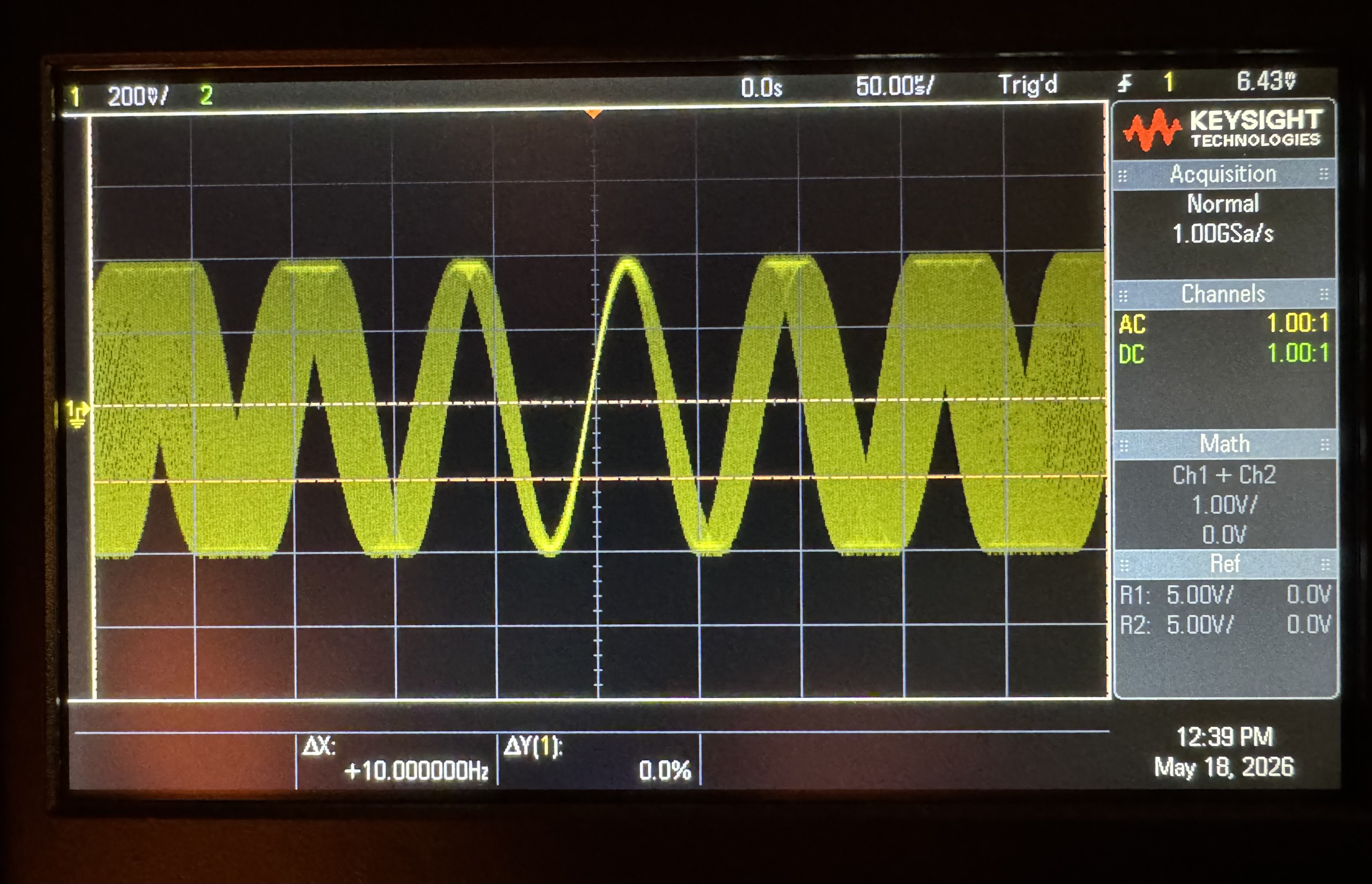
Sweep Triangle:
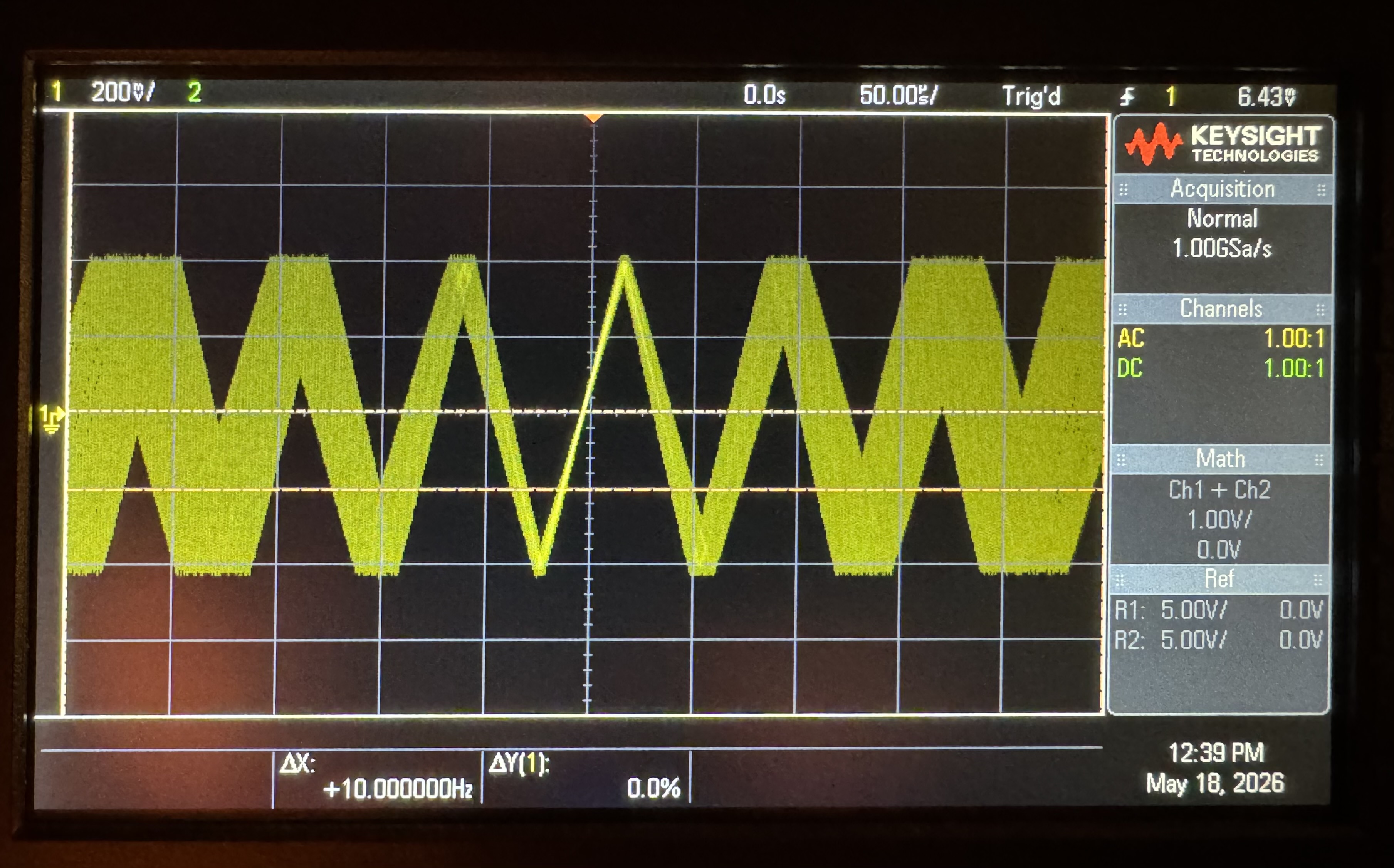
Sweep Square:
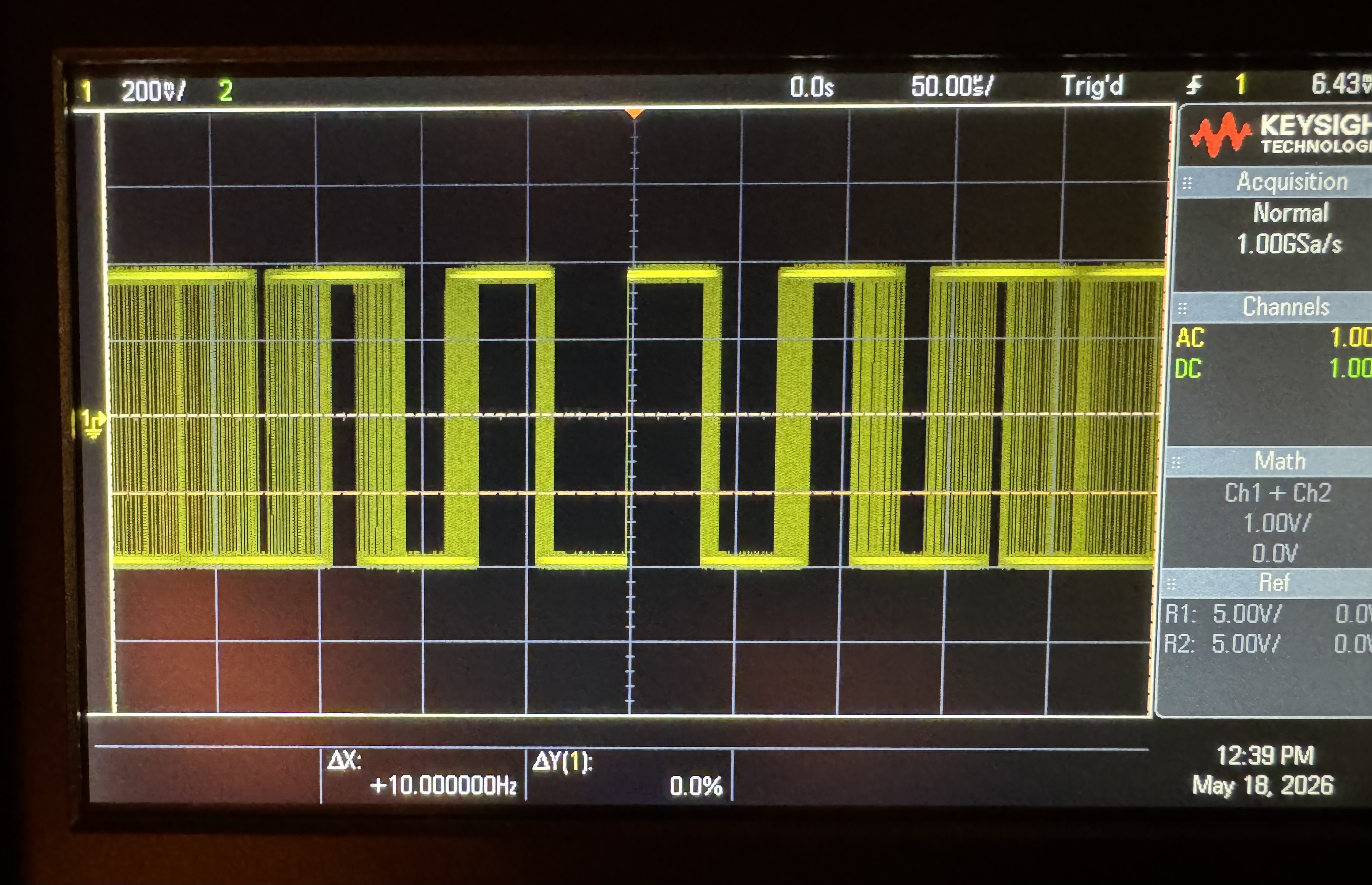
Pulses
Pulses can be done in single or multiple bursts, depending on your configured settings. To initiate pulses:
1.) Set the rear panel bottom switch to INT
2.) Set the rear panel top switch to either single or multiple
3.) Rotate the Trigger Switch to the desired phase
4.) Using the FREQUENCY dial, set the desired frequency
5.) Using the RANGE HZ button on the modulation section to set the desired repetition rate
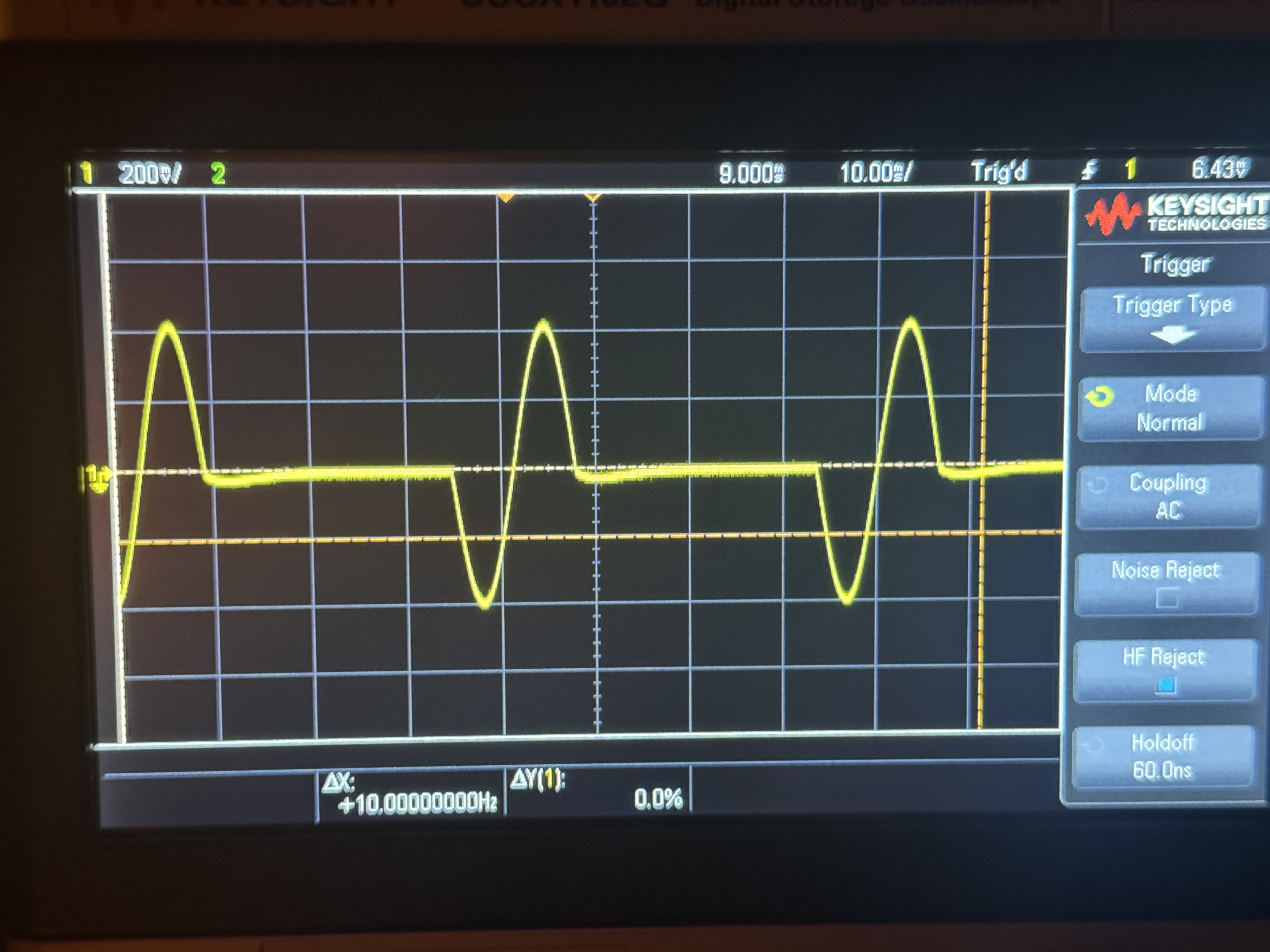
Below are single and multiple pulse examples, with set buttons and dials for each example:
Single Pulse
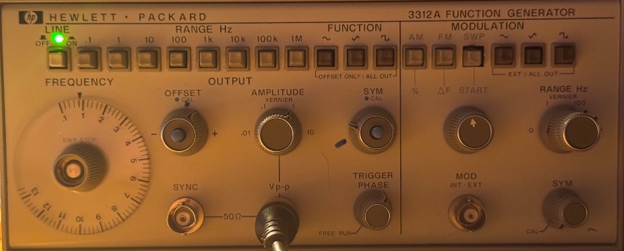
Multiple Pulse
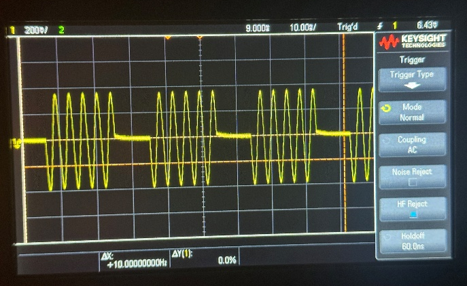
For multiple bursts, a vernier and a RANGE of 100 Hz or higher works best.