
Run Hello World on a ZC702
![]()
This post shows how run Hello World on a Xilinx ZC702. It covers: creating a design in Vivado, exporting the design to the SDK and running Hello World on the dual-core ARM Cortex-A9 processor in the Zynq-7000.
Contains
Part I: Build a PS and Generate a Bitstream
Part II: Export Hardware Design and the Open SDK
Parr III: Set up the ZC702
Part IV: Set up the Terminal
Part V: Run HelloWorld
Part VI: Debug HelloWorld
Note
This write up follows the steps presented in Zynq-7000 All Programmable SoC: Embedded Design Tutorial and adds corrections, clarifications and additional information.
Versions
-
Vivado 2018.2 available @ [link] (install the free WebPACK edition)
-
Windows 7 SP1
Part I: Build a PS and Generate a Bitstream
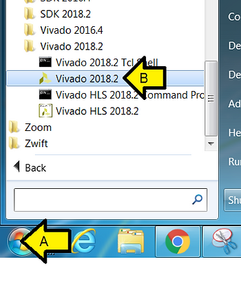
Step 1: Start Vivado 2018.2
A. Click Start
B. Click Vivado 2018.2
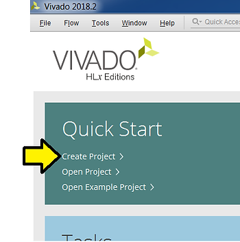
Step 2: Click Create Project
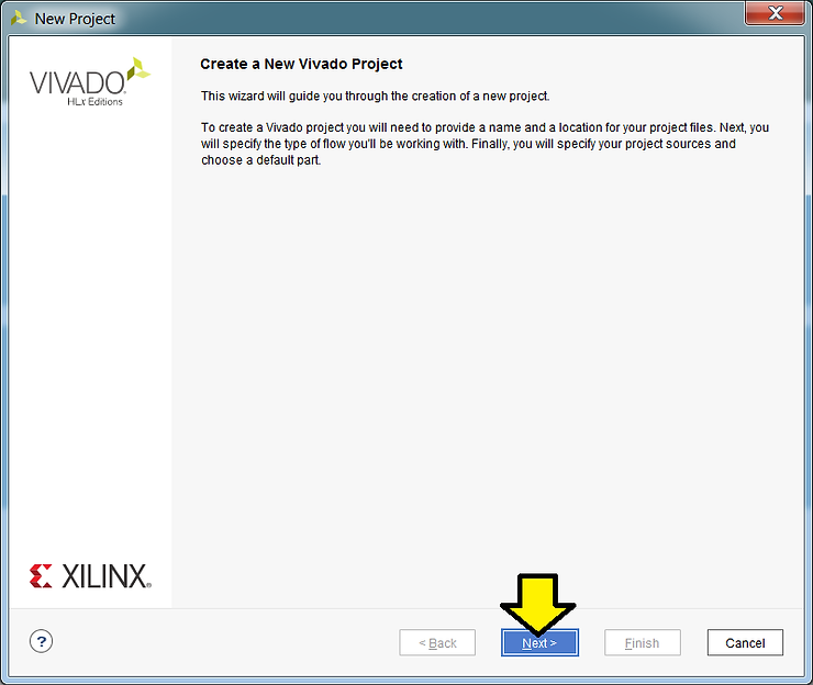
Step 3: Click Next
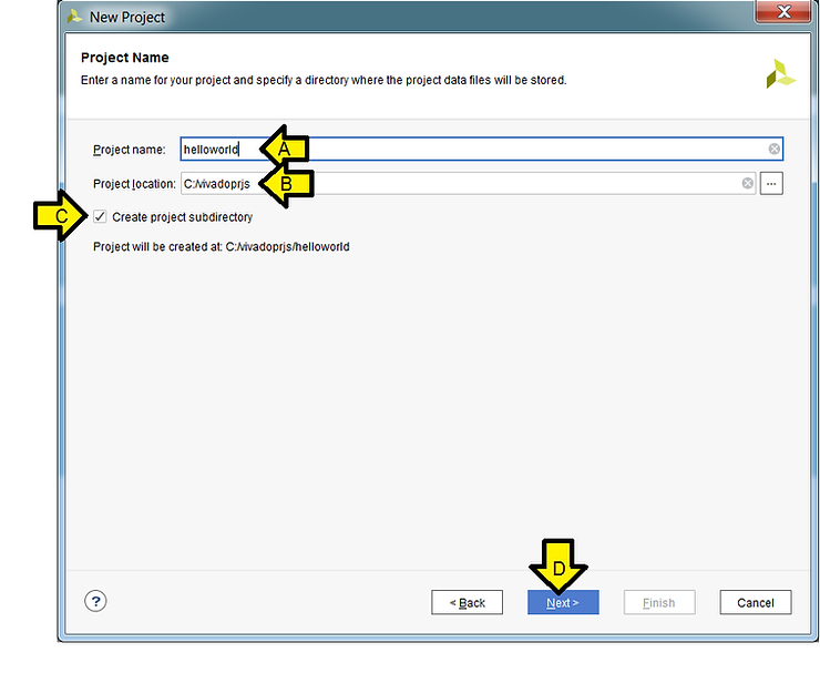
Step 4:
A. Set Project name to helloworld (always use a name without spaces [moreinfo])
B. Set Project location to C:/vivadoprjs (keep paths less than 200 chars)
C. Check the Create project subdirectory checkbox
D. Click Next
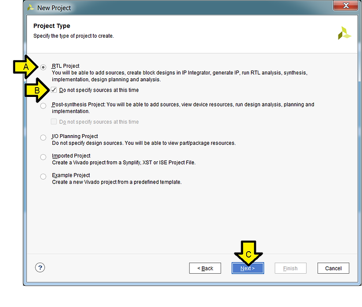
Step 5:
A. Select the RTL Project radio button if its not selected
B. Check the Do not specify source at this time checkbox
C. Click Next
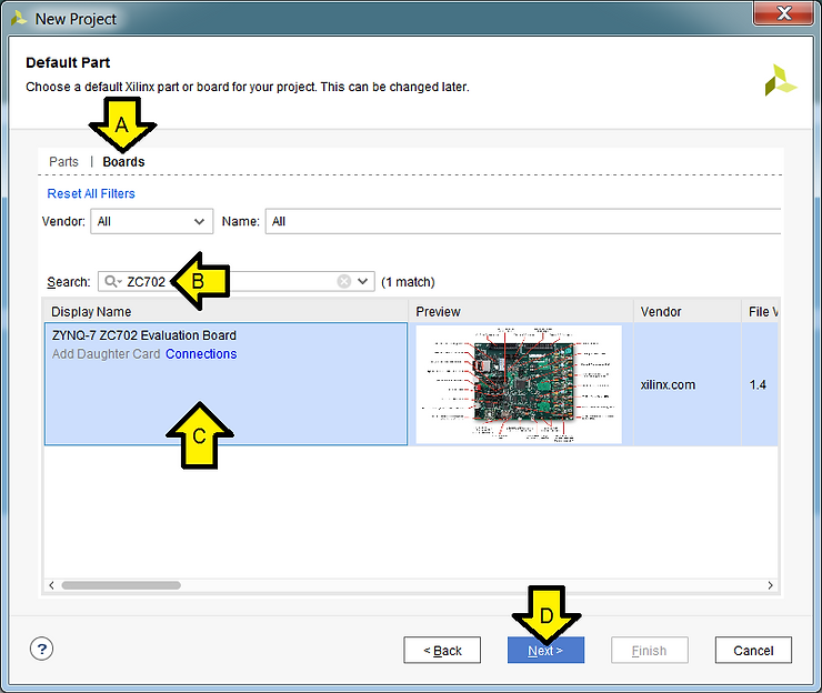
Step 6:
A. Click Boards
B. Type ZC702
C. Click the ZYNQ-7 ZC702 Evaluation Board
D. Click Next
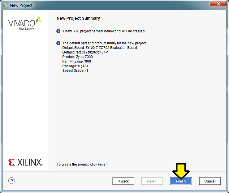
Step 7: Click Finish
Text Listed, More Info and Links to Docs
New Project Summary
A new RTL project named ‘helloworld’ will be created.
The default part and product family for the new project:
Default Board: ZYNQ-7 ZC702 Evaluation Board
Default Part: xc7z020clg484-1 [speedgrade and part # decode (datasheet p.23)]
Product: Zynq-7000 [product page]
Family: Zynq-7000
Package: clg484 [Pinout Files & Packaging and Pinout p.79]
Speed Grade: -1
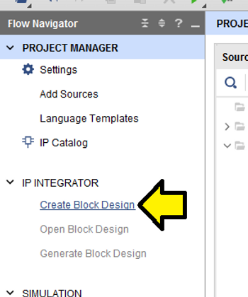
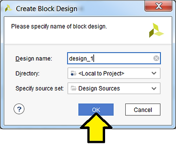
Step 8: Click Create Block Design
Step 9: Use defaults and click OK
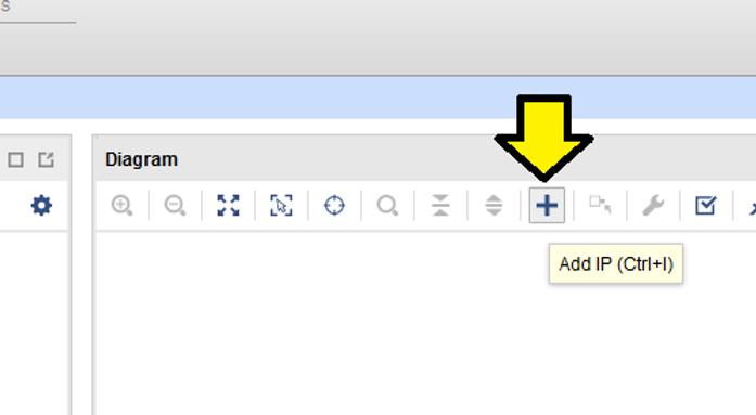
Step 10: Click + to add IP (or Ctrl-I)
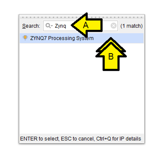
Step 11:
A. Type Zynq
B. Double click on ZYNQ7 Processing System
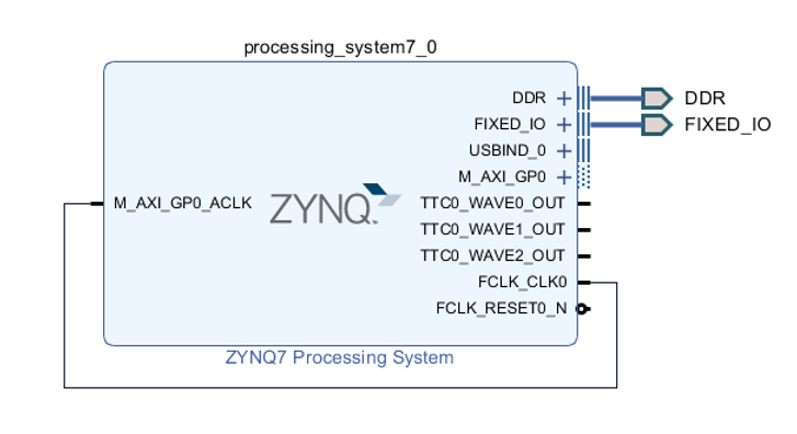
You’ll see the Xilinx LogiCORE™ IP Processing System 7 core [doc]:
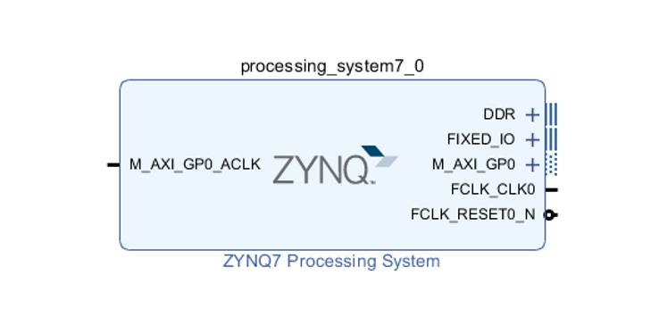
Interfaces:
M_AXI_GP0_ACLK (input, global clock, all signals sampled on rising edge of the global clock)
DDR
FIXED_IO
M_AXI_GP0
FCLK_CLK0 (output, fabric aka PL clock, clock for the PL)
FCLK_RESET0_N
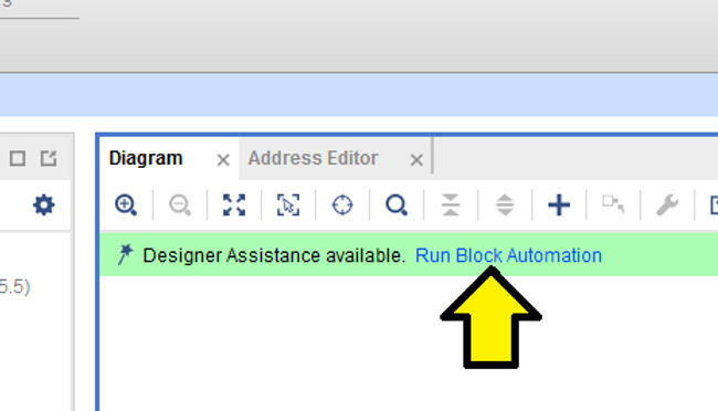
Step 12: Click Run Block Automation
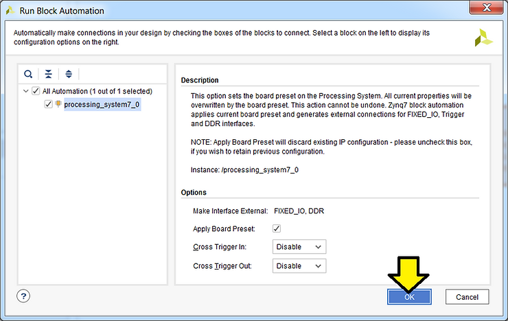
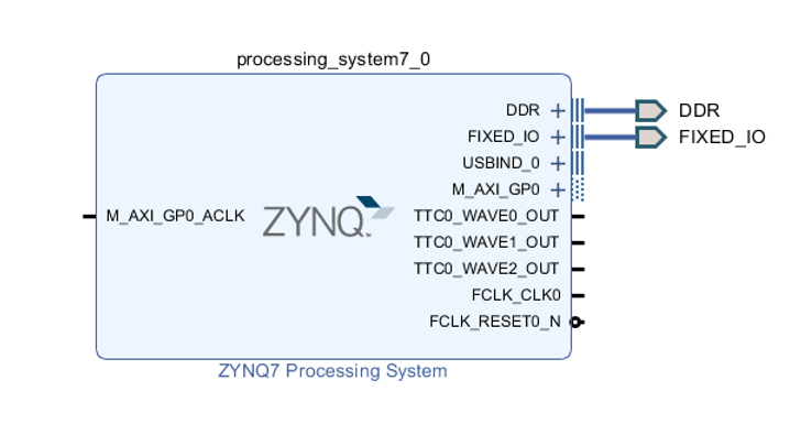
Step 13: Use defaults and click OK
You’ll see:
Step 14: Connect the PL clock (FCLK_CLK0) to the global clock (M_AXI_GP0_ACLK)
A. Click and hold on FCLK_CLK0
B. Drag the connection to M_AXI_GP0_ACLK and release mouse button
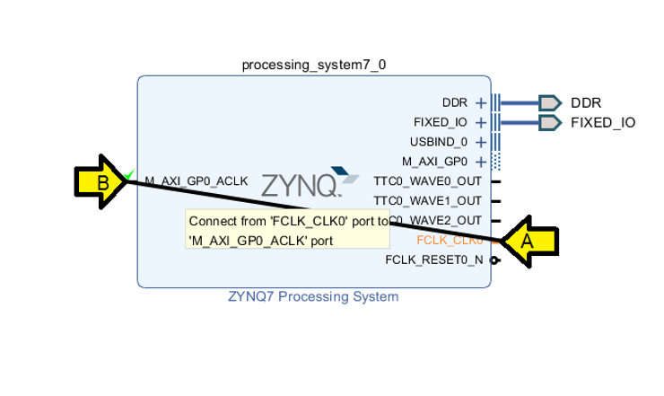
You should see:
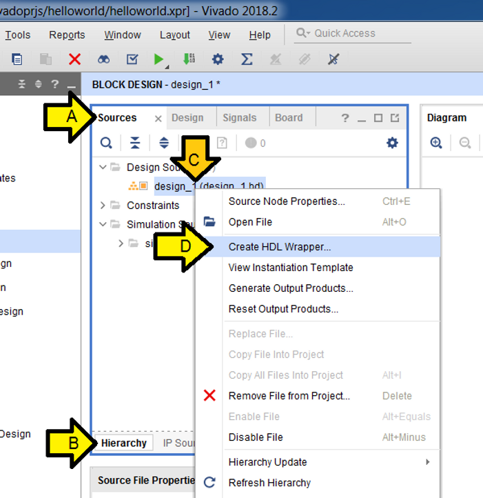
Step 15: Create an HDL Wrapper
A. Click Sources
B. Click Hierarchy
C. Right-click design_1 (design_1.bd)
D. Click Create HDL Wrapper…
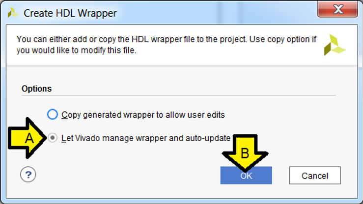
Step 16:
A. Leave or select Let Vivado manage wrapper and auto-update
B. Click OK
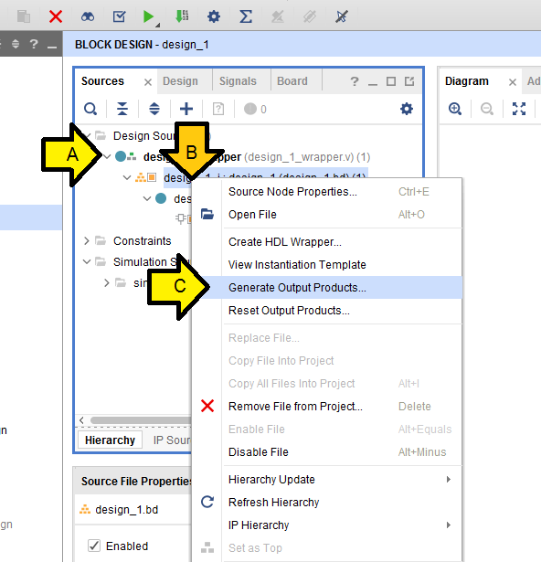
Step 17:
A. Click to expand design_1_wrapper (design_1_wrapper.v)(1)
B. Right-click on design_1_i: design_1 (design_1.bd)(1)
C. Click Generate Output Products…
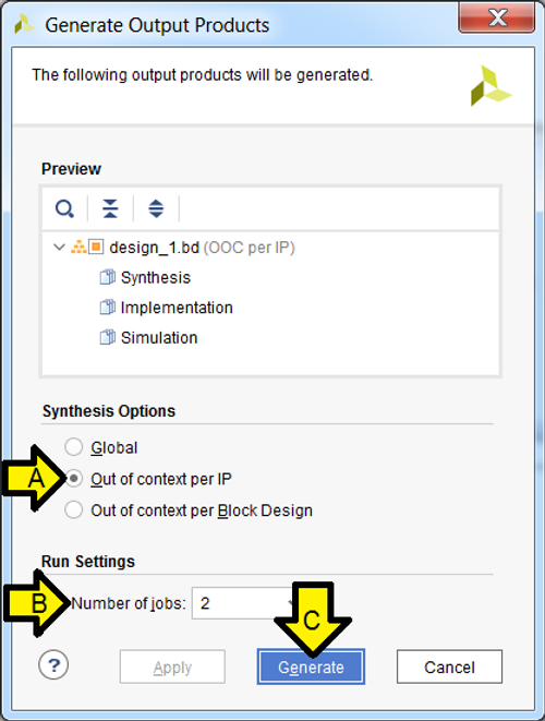
Step 18:
A. Leave selected or select Out of context per IP
B. Leave Number of jobs at 2
C. Click Generate
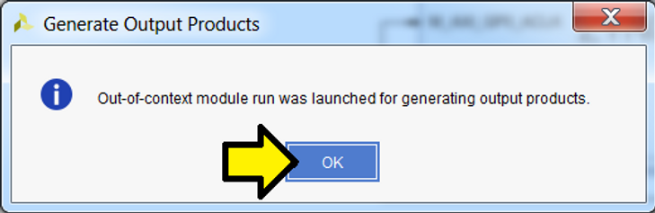
Step 19: Click OK and let the operation complete
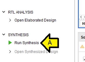
Step 20: Click Run Synthesis
Step 21: Use the defaults and click OK

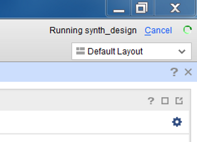
Wait for synth_design to complete
Step 22:
A. Leave selected or select Run Implementation
B. Click OK
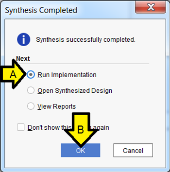
Step 23: Use the defaults and click OK
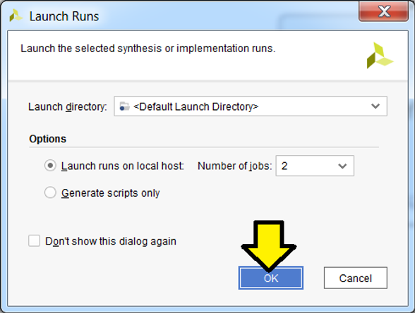
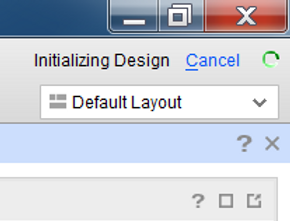
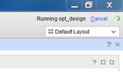
Wait for the operation to complete:
Complete:
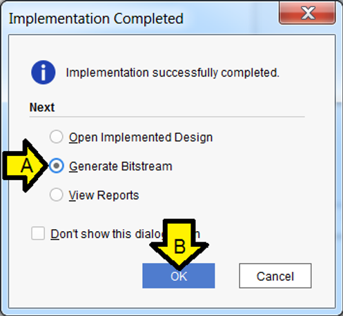
Step 23:
A. Select Generate Bitstream
B. Click OK
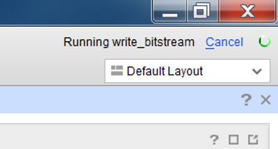
Step 24: Use the defaults and click OK
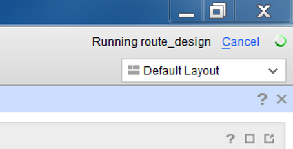
Wait for the operation to complete:
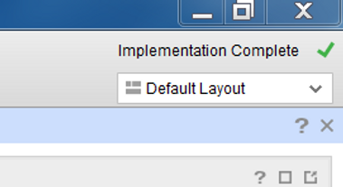
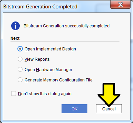
Complete:
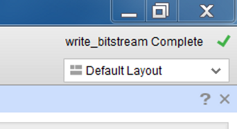
Step 25: Click Cancel
Part II: Export Hardware Design and the Open SDK
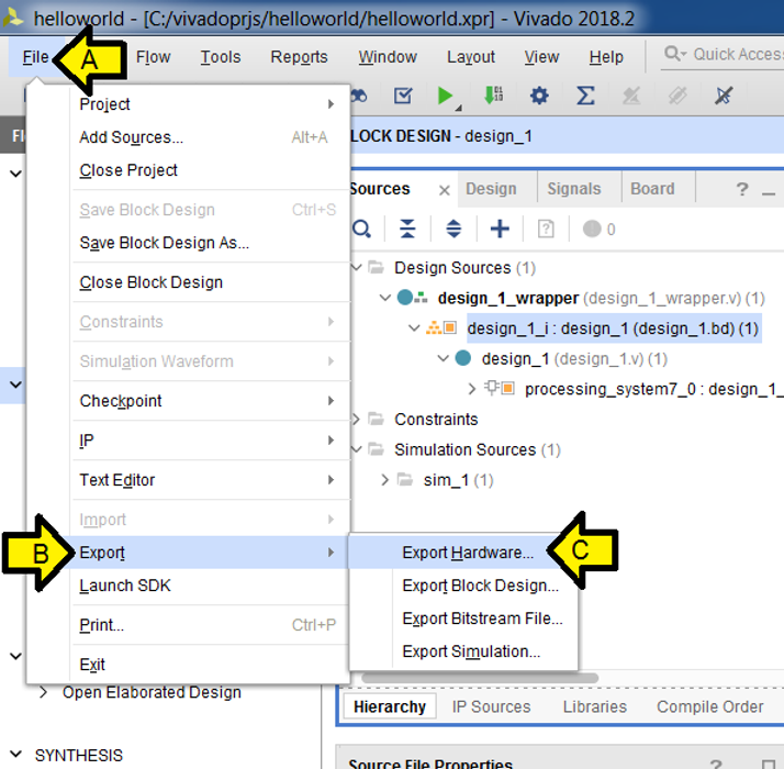
Step 1:
A. Click File
B. Click Export
C. Click Export Hardware
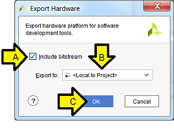
Step 2:
A. Click the Include bitstream checkbox
B. Leave **
C. Click OK
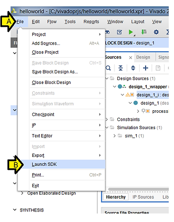
Step 3:
A. Click File
B. Click Launch SDK
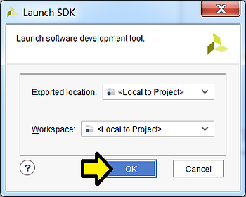
Step 4: Use defaults and click OK
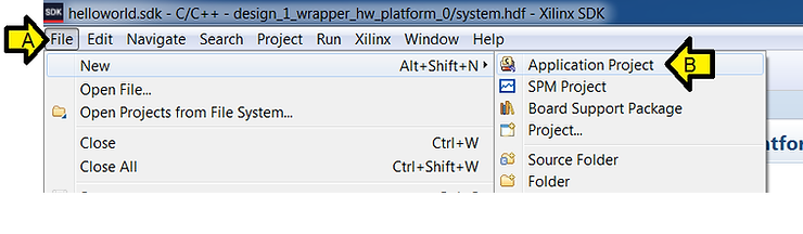
Step 5:
A. Click File
B. Click Application Project
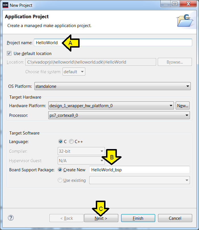
Step 6:
A. Type HelloWorld for Project name
B. See HelloWorld_bsp autopopulate
C. Click Next
Step 7:
A. Ensure Hello World is selected (it should be)
B. Click Finish
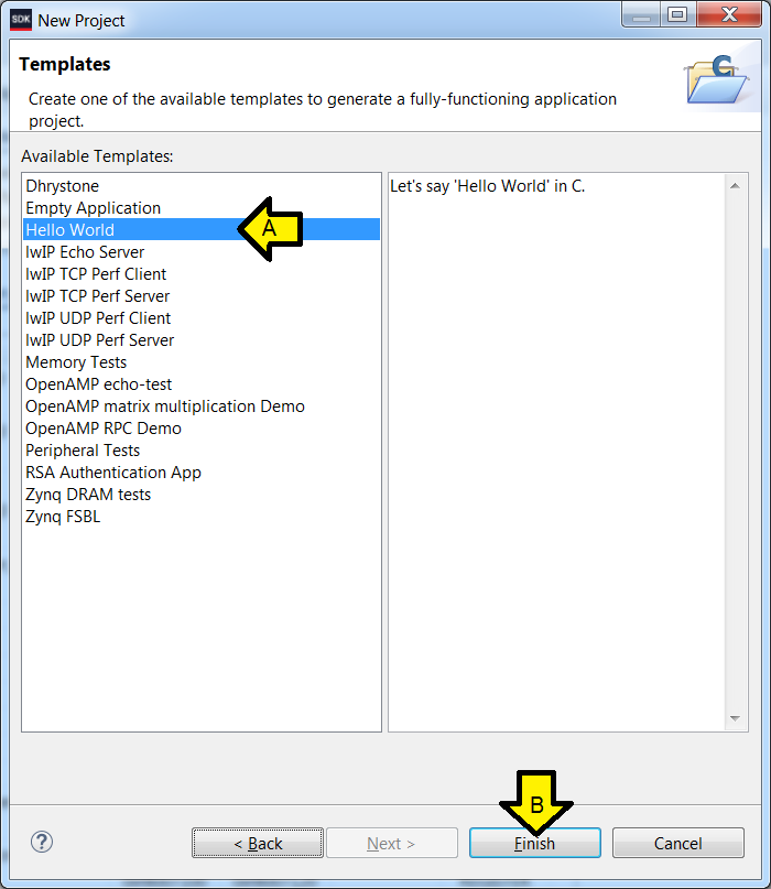
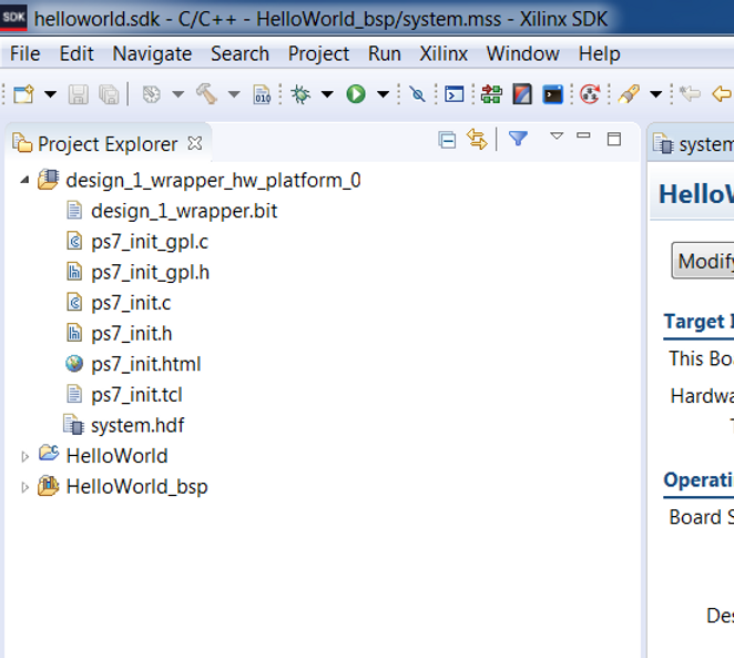
You should see:
Part III: Set up the ZC702
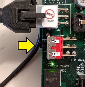
Step 1: Set SW16 to JTAG mode [mode documentation see p.16]
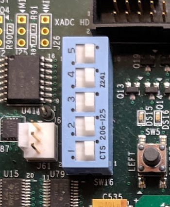
For the rest of the jumpers see the high-resolution photo of the board in the correct state at [link].
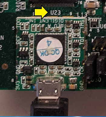
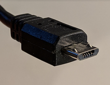
Step 2: Connect a Micro-B to Type-A (host connection) USB cable from U23 (Diglent USB JTAG interface) to the host PC
U23:
Micro-B connector:
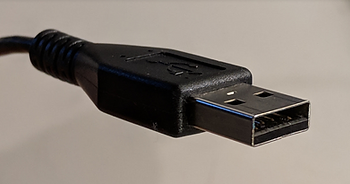
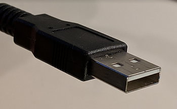
Type-A connector:
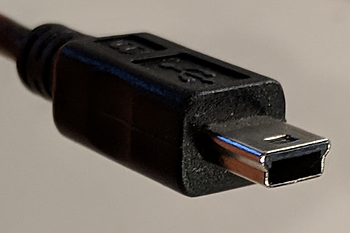
Step 3: Connect a Mini-B to Type-A (host connection) USB cable from J17 (CP2103GM USB-to_UART Bridge) to the host PC.
J17:
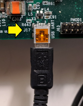
Mini-B connector:
Type-A connector:
Step 4: Power on the board (you’ll need to power on the board to see the USB-to-UART device in the next step).
Part IV: Set up the Terminal
Step 1: Install the Silicon Labs CP210x USB to UART Bridge VCP Drivers
A. Goto [link]
B. Download and unzip the correct installer
C. Install the driver (I did not need to restart on Windows 7 SP1)
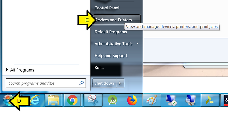
D. Click Windows
E. Click Devices and Printers
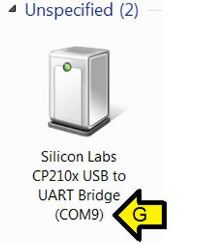
F. You should see Silicon Labs CP210x USB to UART Bridge
G. Note the COM port (you’ll need this later)
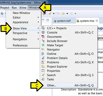
Step 2:
A. Click Window
B. Click Show View
C. Click Other
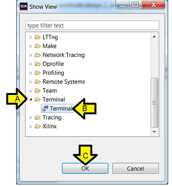
Step 3:
A. Expand Terminal
B. Click Terminal
C. Click OK
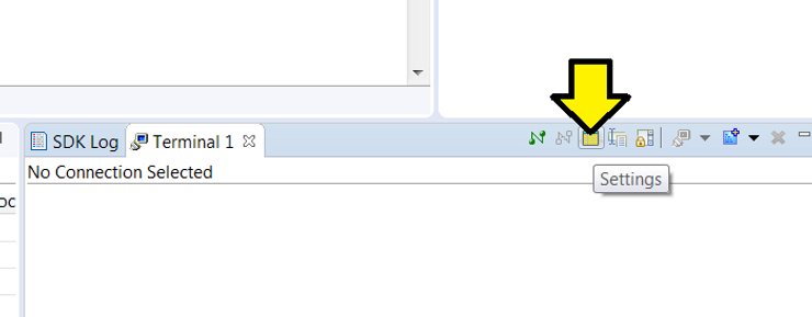
Step 4: Click Settings
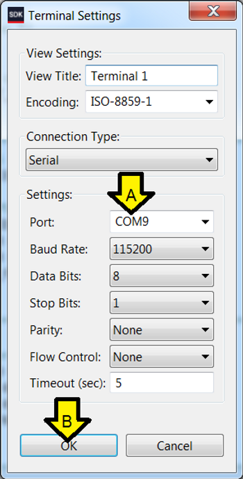
Step 5:
A. Use the COM port listed in Devices and Printers (or type it in: COM9 for instance)
B. Click OK
Part V: Run HelloWorld
Step 1: Run Debug once
A. Right click HelloWorld
B. Click Debug As
C. Click Launch on Hardware (System Debugger)
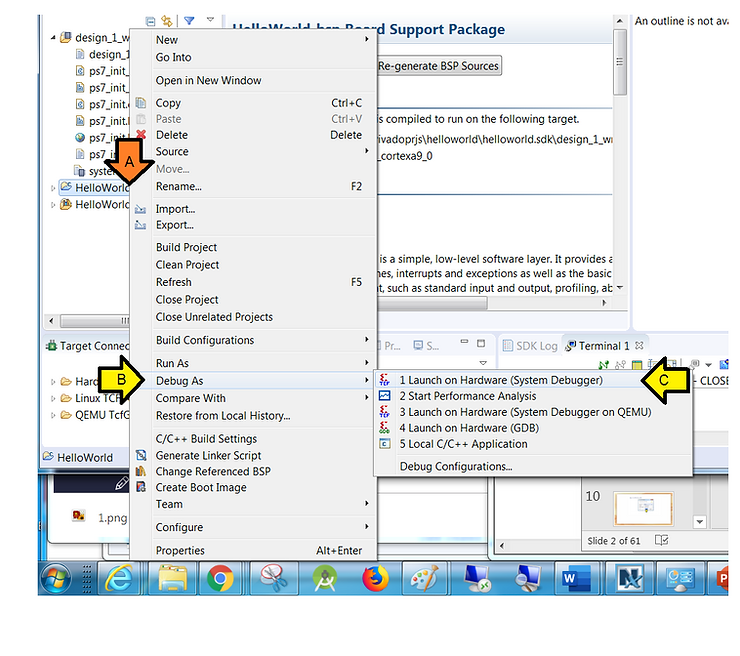
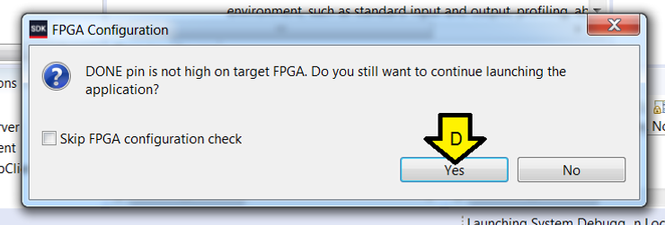
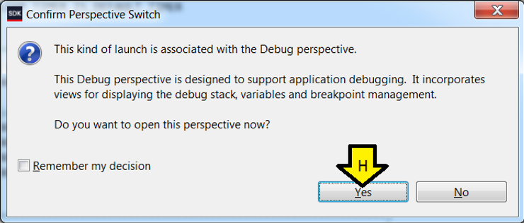
D. Click Yes
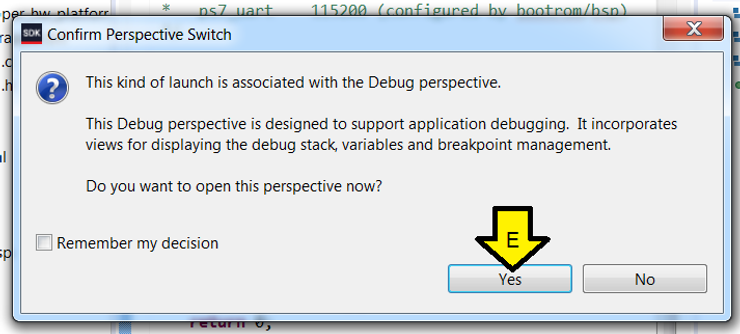
E. Click Yes
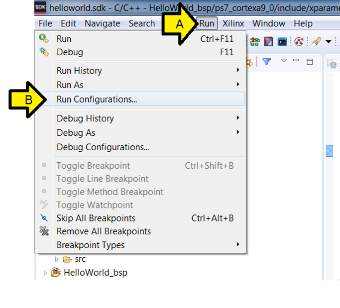
Step 2:
A. Click Run
B. Click Run Configurations…
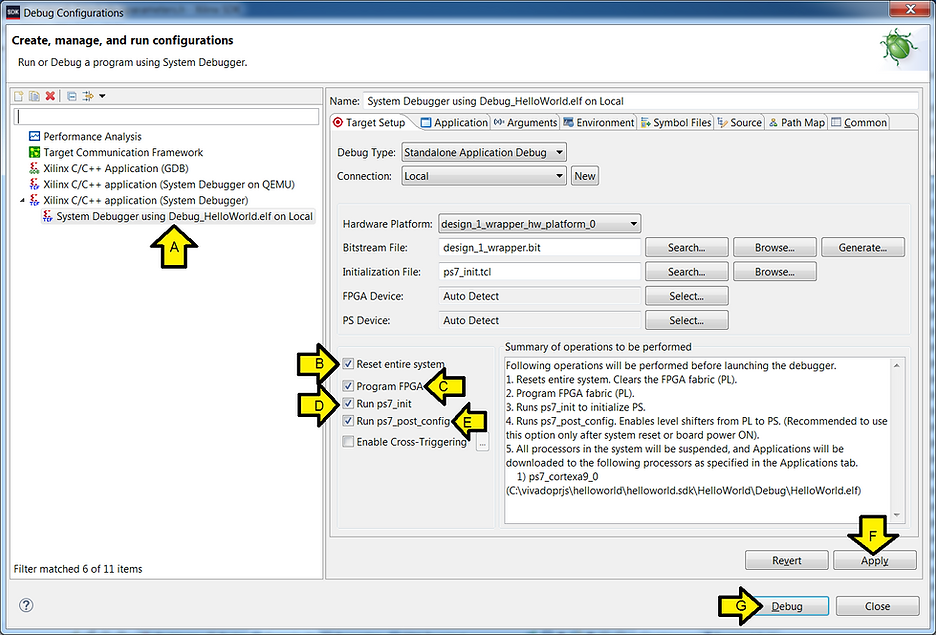
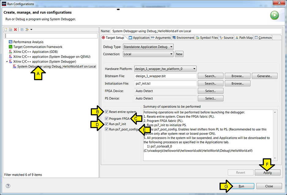
Step 3:
A. Make sure System Debugger using Debug_HelloWorld.elf on Local is selected
B. Check the Reset entire system check box
C. Check the Program FPGA check box
D. Ensure the Run ps7_init check box is checked
E. Ensure the Run ps7_post_config is checked
F. Click Apply
G. Click Run
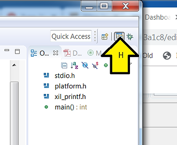
H. Switch back to the C/C++ View
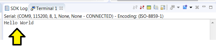
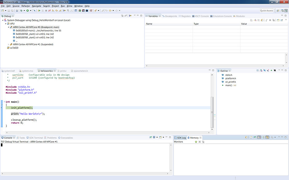
You should see:
Step 4: Run the program again
A. Click Run
B. Click Run (this will use the Run Config you set up previously)
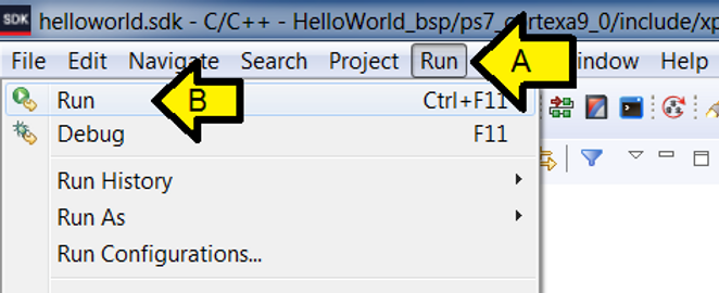
C. Click OK
You should see another Hello World:
Part VI: Debug HelloWorld
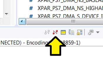
Step 1: Click to disconnect Run terminal
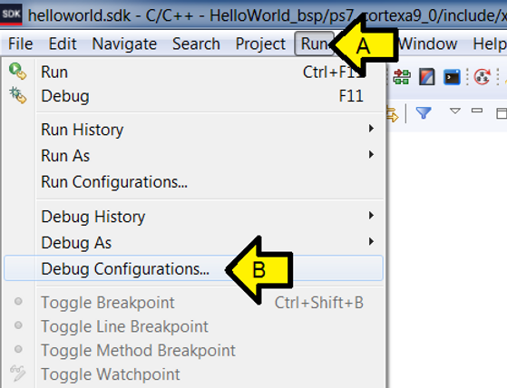
Step 2:
A. Click Run
B. Click Debug Configurations…
Step 3:
A. Make sure System Debugger using Debug_HelloWorld.elf on Local is selected
B. Make sure the Reset entire system check box is checked
C. Make sure theProgram FPGA check box is checked
D. Ensure the Run ps7_init check box is checked
E. Ensure the Run ps7_post_config is checked
F. Click Apply if anything changed (the Apply button will be grayed out if no changes were needed).
G. Click Debug
H. Click Yes
You should see:
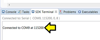
Step 4: Connect the serial port
A. Click SDK Terminal
B. Click the ’+’ (Connect to serial port.)
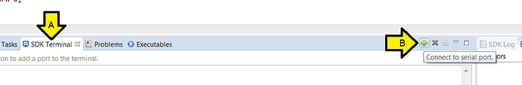
C. Use these settings and click OK
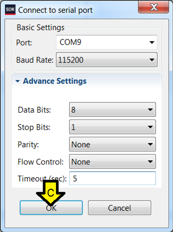
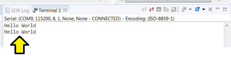
You should see:
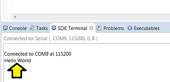
Step 5: Click Resume (F8)
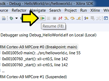
You should see:
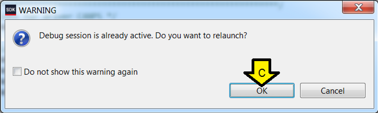
Step 6: Restart Debug
A. Click Run
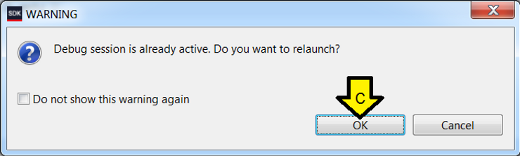
B. Click Debug (this will use the Debug Config you set up previously)
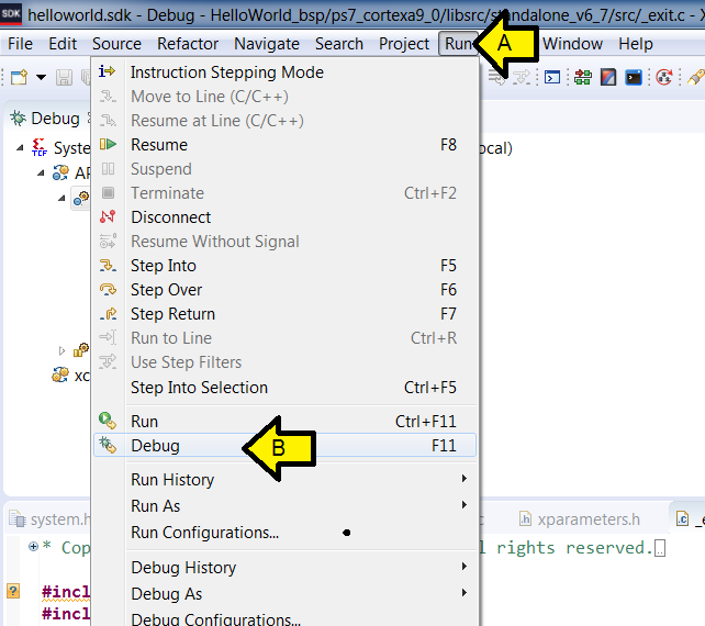
C. Click OK
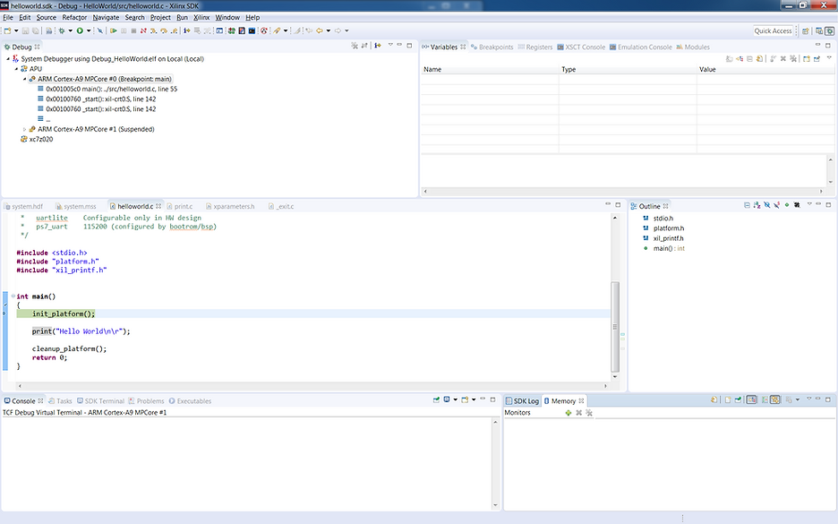
You should again see:
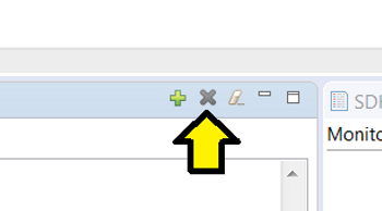
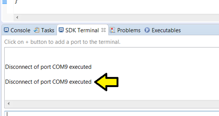
Note: to disconnect the debuggers serial port click here:
You should see:
References
-
2018.2 Zynq-7000 All Programmable SoC: Embedded Design Tutorial (UG1165) @ [link] (p.15 to 30)
-
Xilinx logo found via https://twitter.com/xilinxinc at [link]