
MicroBlaze TMR 2019.1
![]()
In this post I will briefly explain how to put 3 MicroBlaze soft-core CPUs on Nexys 4 DDR FPGA (Xilinx Artix 7 FPGA) and use Triple Modular Redundancy (TMR) block on GPIO!
Add the following IPs into a block design:
-
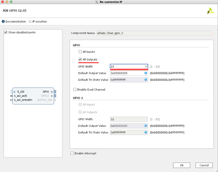
AXI GPIO
-
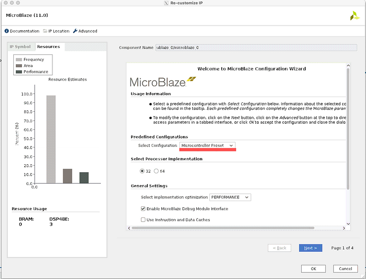
Microblaze
GPIO config: 16 bit output
MicroBlaze config: Select Configuration-> Microcontroller Preset
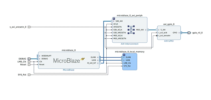
ublaze block design
You will end up with something similar.
After configuring all blocks as explained above - create a ublaze hierarchy
-
Select all blocks
-
Right click, Create Hierarchy
-
OK
-
Copy-paste it twice, connect signals as shown below
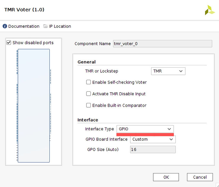
Add TMR Voter config: (Set Interface Type to GPIO)
Top block design
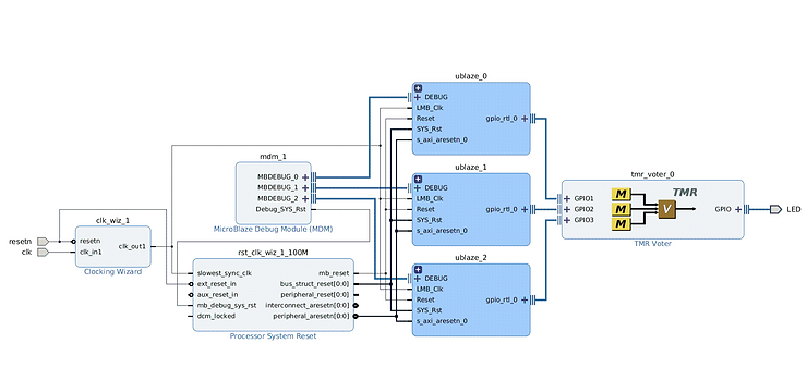
Create HDL Wrapper:
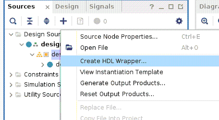
This will result in something like:
//Copyright 1986-2019 Xilinx, Inc. All Rights Reserved.
//--------------------------------------------------------------------------------
//Tool Version: Vivado v.2019.1 (lin64) Build 2552052 Fri May 24 14:47:09 MDT 2019
//Date        : Thu Mar 11 20:17:31 2021
//Host        : predator running 64-bit Ubuntu 18.04.5 LTS
//Command     : generate_target design_1_wrapper.bd
//Design      : design_1_wrapper
//Purpose     : IP block netlist
//--------------------------------------------------------------------------------
`timescale 1 ps / 1 ps

module design_1_wrapper
   (LED_tri_o,
    clk,
    resetn);
  output [15:0]LED_tri_o;
  input clk;
  input resetn;

  wire [15:0]LED_tri_o;
  wire clk;
  wire resetn;

  design_1 design_1_i
       (.LED_tri_o(LED_tri_o),
        .clk(clk),
        .resetn(resetn));
endmodule
Modify your constraints file like this:
Nexys-4-DDR-Master.xdc
## This file is a general .xdc for the Nexys4 DDR Rev. C
## To use it in a project:
## - uncomment the lines corresponding to used pins
## - rename the used ports (in each line, after get_ports) according to the top level signal names in the project

## Clock signal
set_property -dict { PACKAGE_PIN E3    IOSTANDARD LVCMOS33 } [get_ports { clk }]; #IO_L12P_T1_MRCC_35 Sch=clk100mhz
create_clock -add -name sys_clk_pin -period 10.00 -waveform {0 5} [get_ports {clk}];


## LEDs

set_property -dict { PACKAGE_PIN H17   IOSTANDARD LVCMOS33 } [get_ports { LED_tri_o[0] }]; #IO_L18P_T2_A24_15 Sch=led[0]
set_property -dict { PACKAGE_PIN K15   IOSTANDARD LVCMOS33 } [get_ports { LED_tri_o[1] }]; #IO_L24P_T3_RS1_15 Sch=led[1]
set_property -dict { PACKAGE_PIN J13   IOSTANDARD LVCMOS33 } [get_ports { LED_tri_o[2] }]; #IO_L17N_T2_A25_15 Sch=led[2]
set_property -dict { PACKAGE_PIN N14   IOSTANDARD LVCMOS33 } [get_ports { LED_tri_o[3] }]; #IO_L8P_T1_D11_14 Sch=led[3]
set_property -dict { PACKAGE_PIN R18   IOSTANDARD LVCMOS33 } [get_ports { LED_tri_o[4] }]; #IO_L7P_T1_D09_14 Sch=led[4]
set_property -dict { PACKAGE_PIN V17   IOSTANDARD LVCMOS33 } [get_ports { LED_tri_o[5] }]; #IO_L18N_T2_A11_D27_14 Sch=led[5]
set_property -dict { PACKAGE_PIN U17   IOSTANDARD LVCMOS33 } [get_ports { LED_tri_o[6] }]; #IO_L17P_T2_A14_D30_14 Sch=led[6]
set_property -dict { PACKAGE_PIN U16   IOSTANDARD LVCMOS33 } [get_ports { LED_tri_o[7] }]; #IO_L18P_T2_A12_D28_14 Sch=led[7]
set_property -dict { PACKAGE_PIN V16   IOSTANDARD LVCMOS33 } [get_ports { LED_tri_o[8] }]; #IO_L16N_T2_A15_D31_14 Sch=led[8]
set_property -dict { PACKAGE_PIN T15   IOSTANDARD LVCMOS33 } [get_ports { LED_tri_o[9] }]; #IO_L14N_T2_SRCC_14 Sch=led[9]
set_property -dict { PACKAGE_PIN U14   IOSTANDARD LVCMOS33 } [get_ports { LED_tri_o[10] }]; #IO_L22P_T3_A05_D21_14 Sch=led[10]
set_property -dict { PACKAGE_PIN T16   IOSTANDARD LVCMOS33 } [get_ports { LED_tri_o[11] }]; #IO_L15N_T2_DQS_DOUT_CSO_B_14 Sch=led[11]
set_property -dict { PACKAGE_PIN V15   IOSTANDARD LVCMOS33 } [get_ports { LED_tri_o[12] }]; #IO_L16P_T2_CSI_B_14 Sch=led[12]
set_property -dict { PACKAGE_PIN V14   IOSTANDARD LVCMOS33 } [get_ports { LED_tri_o[13] }]; #IO_L22N_T3_A04_D20_14 Sch=led[13]
set_property -dict { PACKAGE_PIN V12   IOSTANDARD LVCMOS33 } [get_ports { LED_tri_o[14] }]; #IO_L20N_T3_A07_D23_14 Sch=led[14]
set_property -dict { PACKAGE_PIN V11   IOSTANDARD LVCMOS33 } [get_ports { LED_tri_o[15] }]; #IO_L21N_T3_DQS_A06_D22_14 Sch=led[15]


##Buttons

set_property -dict { PACKAGE_PIN C12   IOSTANDARD LVCMOS33 } [get_ports { resetn }]; #IO_L3P_T0_DQS_AD1P_15 Sch=cpu_resetn
Export hardware:
File > Export > Export Hardware > Include bitstream > OK
Open SDK
File > Launch SDK
SDK
Create new application projects:
File > New > Application Project
Configure like this: (ignore my error up-top. I already have this project created)
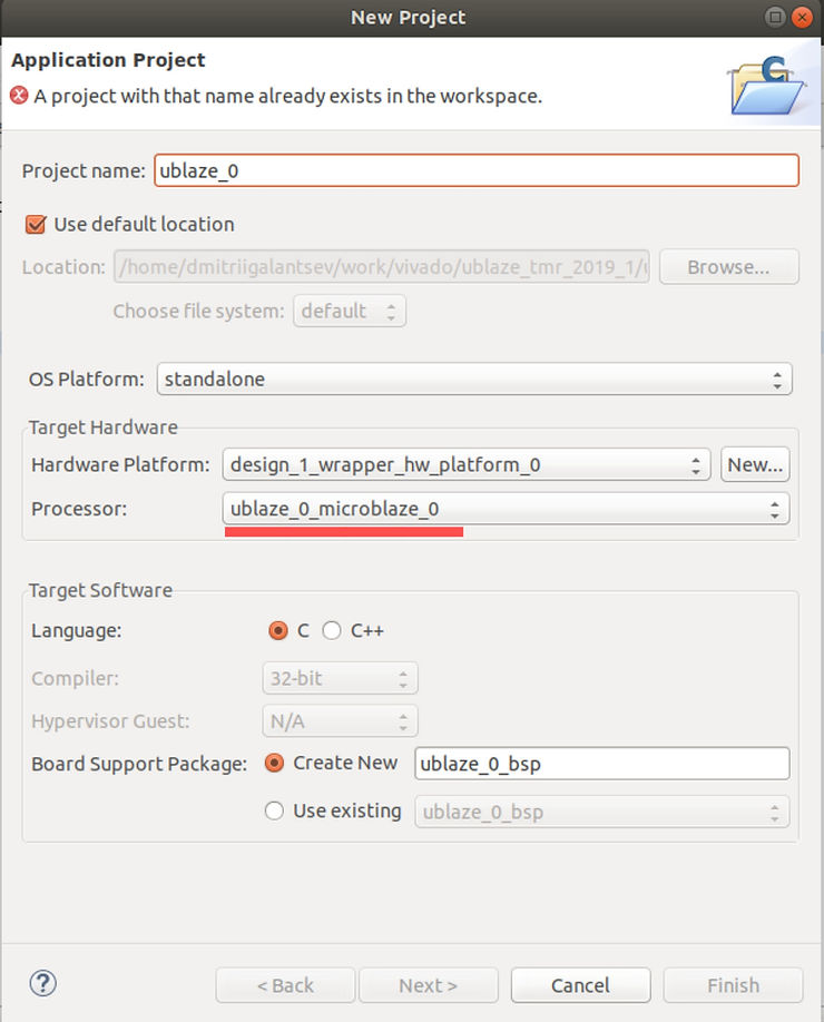
pay close attention to Processor: field!
Create 2 more application projects, name them ublaze_1 and ublaze_2. Use ublaze_1_microblaze_0 and ublaze_2_microblaze_0 for Processor accordingly.
C project
right-click ublaze_0, New > File, name it blink.c
Fill it with:
int main()
{
	int * led_ptr = 0x40000000;
	*led_ptr = 0x4321;
	return 0;
}
Repeat for ublaze_1 and ublaze_2.
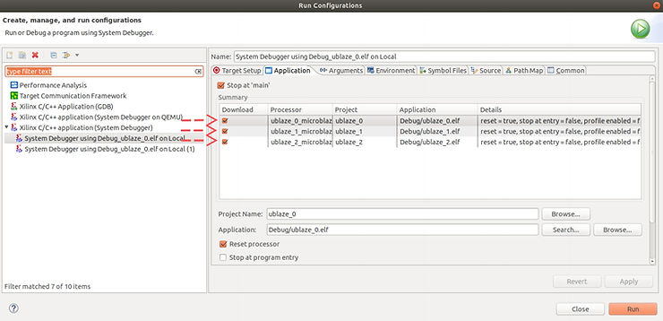
Set Run Configurations
Run > Run Configurations…
Set them up like this:
Program FPGA
Xilinx > Program FPGA > Program
Run application
Run > Run As > Launch On Hardware (System Debugger)
(You might need to select blink.c and run it explicitly)
Your LEDs should light up now!
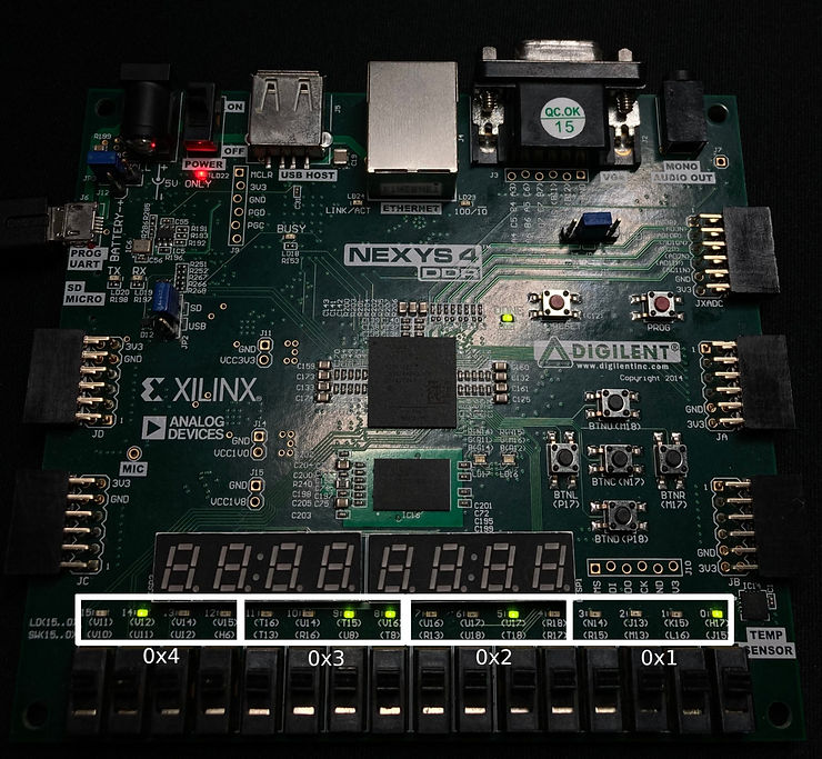
You’re controlling GPIO with microblaze! And if one of them fails - it’s okay. You can still control the LEDs with 2 other ones.
Try to disable one of the microblaze cores, run the other two. Your LEDs will still work as expected.
Video Guide
NOTE: This video slightly different from the rest of the guide (specifically when it comes to signal names). However, it demonstrates the entire process in detail.
https://video.wixstatic.com/video/ceda41_0b5bf7ee8ed34abb97d713569e20b10a/1080p/mp4/file.mp4
TODO
-
Add arrows to screenshots
-
Add explanation of how TMR works
-
Add error injection
Reference
- Nexys 4 ddr constraints: https://github.com/Digilent/digilent-xdc/blob/master/Nexys-4-DDR-Master.xdc
- Xilinx TMR Microblaze reference: https://www.xilinx.com/support/documentation/ip_documentation/tmr/v1_0/pg268-tmr.pdf