
Xilinx’s “Creating an AXI Peripheral in Vivado”: Transcript, Screenshots & Commentary
This post presents a transcript + screenshots of “Creating an AXI Peripheral in Vivado” from Xilinx. It is intended to reinforce learning how to create an AXI peripheral in Vivado and provide a reference to the steps presented. Corrections and tips have also been included to further aid learning. In addition, some screens have been zoomed and cropped to make certain actions more clear.
The original video can be found [here][YouTube].
You Will Learn How To:
-
Use the Create and Package IP feature of Vivado
-
Create an AXI slave that echos registers writes
-
Run the auto testbench to verify the IP
-
Import the IP into a Micro Blaze design
-
Test reads and writes from code running on the MicroBlaze using SDK
Transcript, Screenshots and Commentary
(00:03) Hello and welcome to this Vivado QuickTake video
Note: the title presented, “Packaging Custom IP for use with IP Integrator” does not line up with the title listed on the site hosting the video.
(0:08) In this video you’ll learn how to create an AXI peripheral to which custom logic can be added to create a customer IP using the create and package IP feature of Vivado.
(0:21) This training assumes that you are familiar with designing IP subsystems in IP integrator. You can watch some of the quick take videos on IP Integrator as shown on this slide:
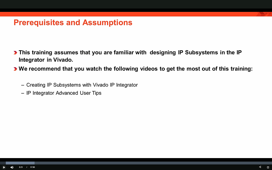
Note: here are the links to the videos:
-
https://www.xilinx.com/video/hardware/ip-subsystems-vivado-ip-integrator.html
-
https://www.xilinx.com/video/hardware/ip-integrator-advanced-user-tips.html
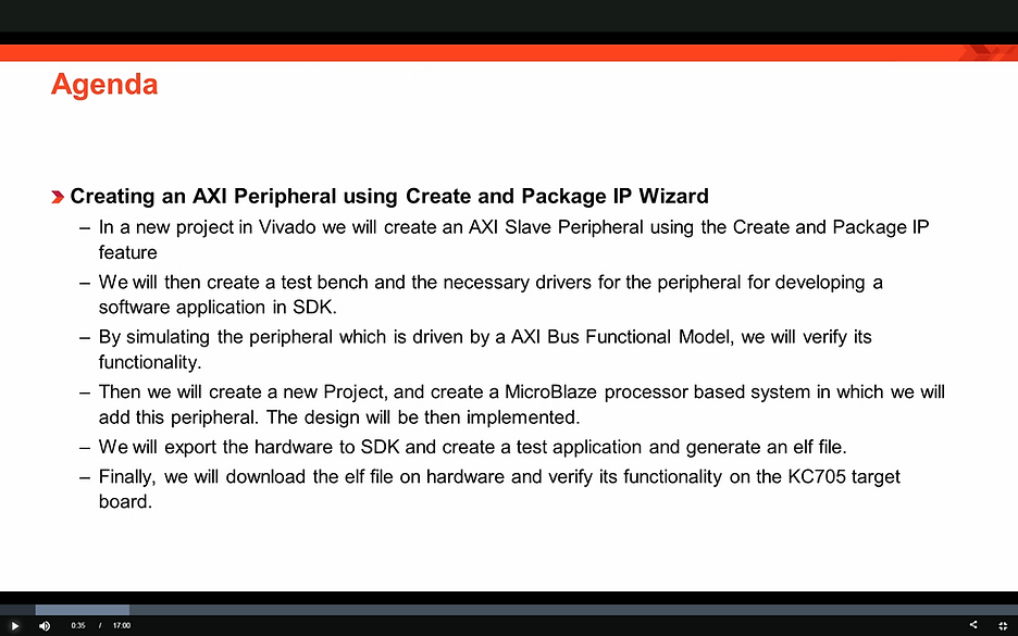
(00:32) In this Quick Take video we’ll create a new project in Vivado using the create and package IP feature, we will then create a slave AXI peripheral. We’ll create a test-bench and necessary drivers for the peripheral for developing a software application in SDK. We’ll simulate the AXI peripheral in Vivado to ensure that the registers of the AXI peripheral can be written and read from using an AXI bus functional simulation model. Then we’ll create a MicroBlaze processor based system in which we will add this custom IP. The design will be then implemented and the bitstream will be generated. We’ll then export the hardware to SDK and create a test application and generate an ELF. Finally, we’ll launch our application on the target board: KC705 and verify its functionality.
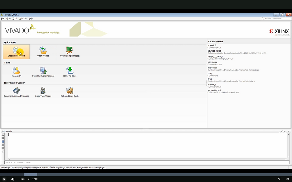
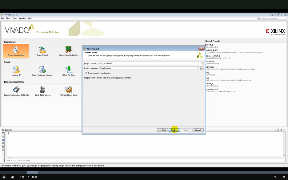
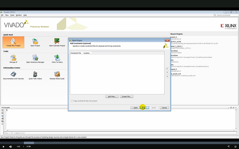
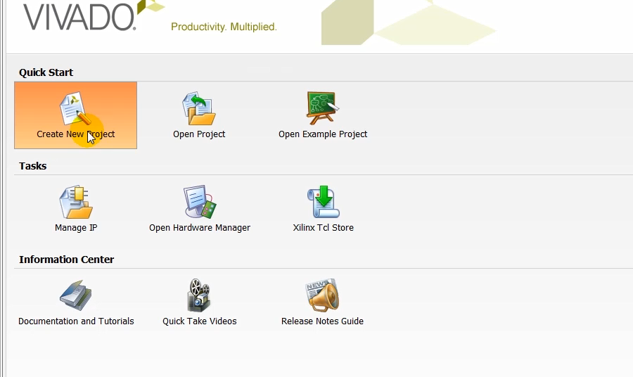
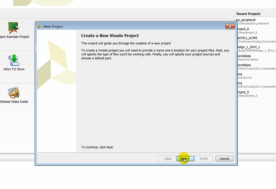
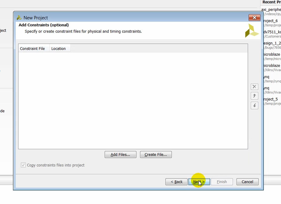
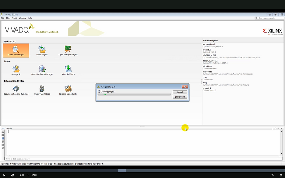
(1:18) We start our design by launching Vivado and creating a new project from the Quick Start page. We’ll name the project and specify the location where the project will be saved. We’ll skip some of the other options for adding existing RTL IP constraints to the project at this time as everything needed for this project will be generated later.
Create a New Project
Step: click Create New Project
Step: click Next
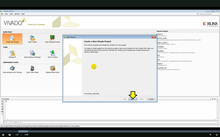
Note: in the video the user taps Enter on the keyboard to go to the Next > screen
Step: enter a Project name, axi_peripheral in this case and click Next
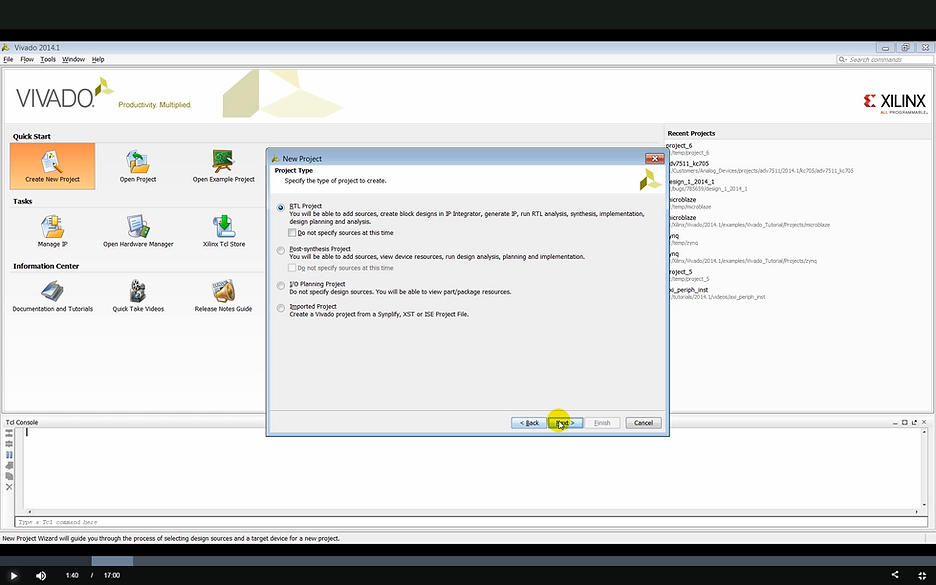
Step: click Next
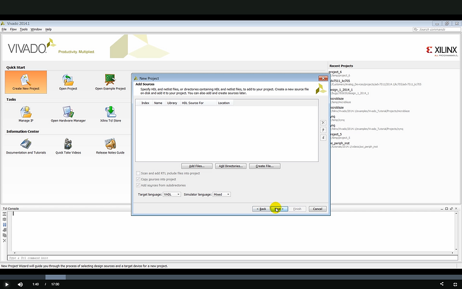
Step: click Next
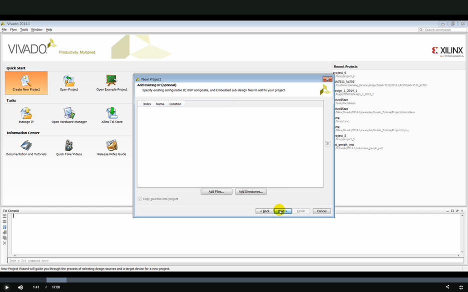
Step: click Next
Step: click Next
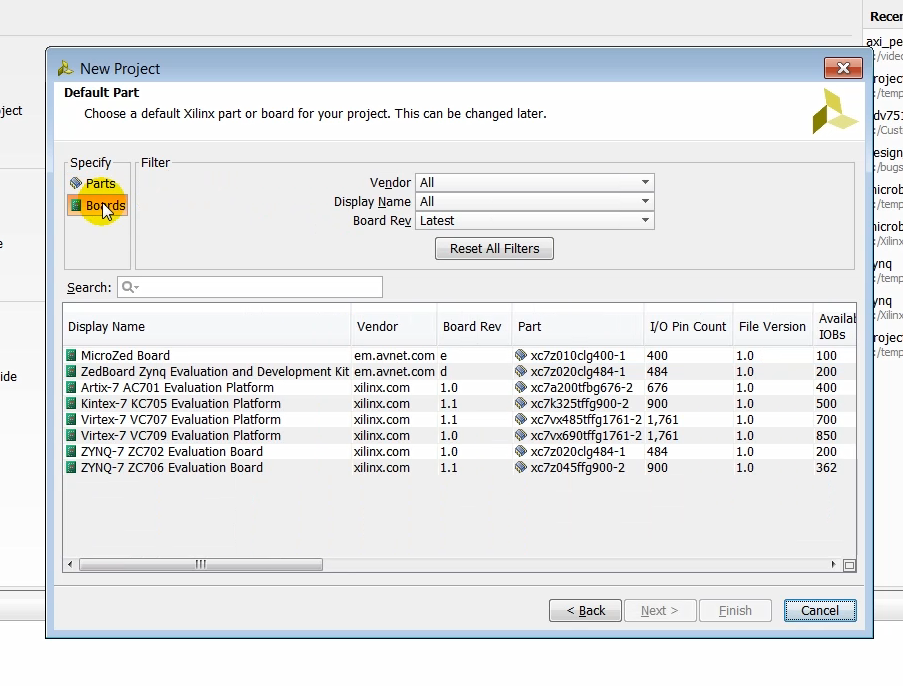
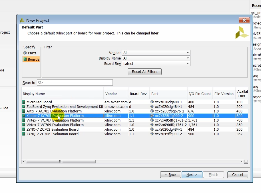
(1:51) We select boards in the default part page. Vivado is board-aware and it knows the physical connections present on our target board. It can thus generate the appropriate physical and timing constraints where our target board based on the interfaces that we choose in our design, we select the KC705 target board here.
Step: click Boards
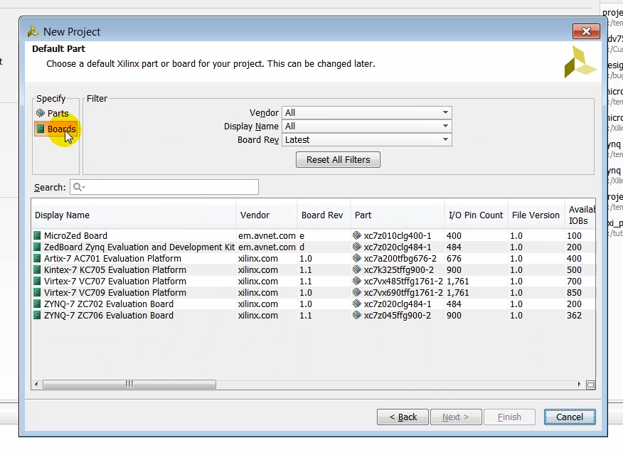
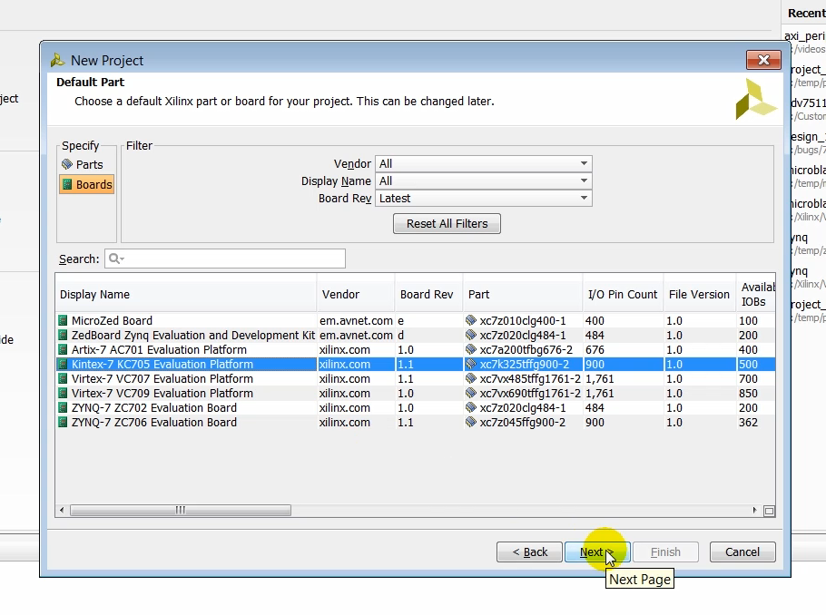
Step: click Kintex-7 KC705 Evaluation Platform
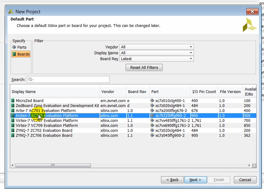
Step: click Next
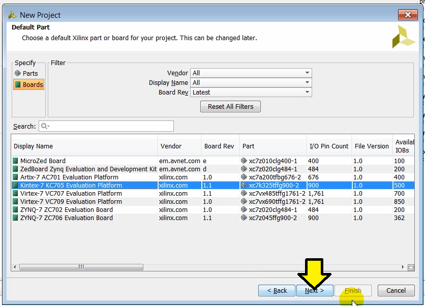
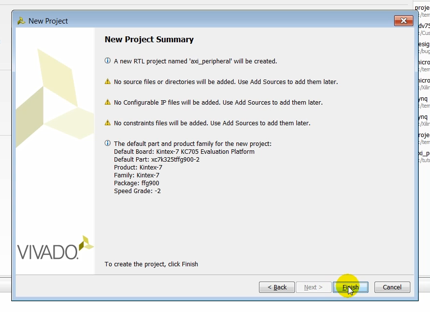
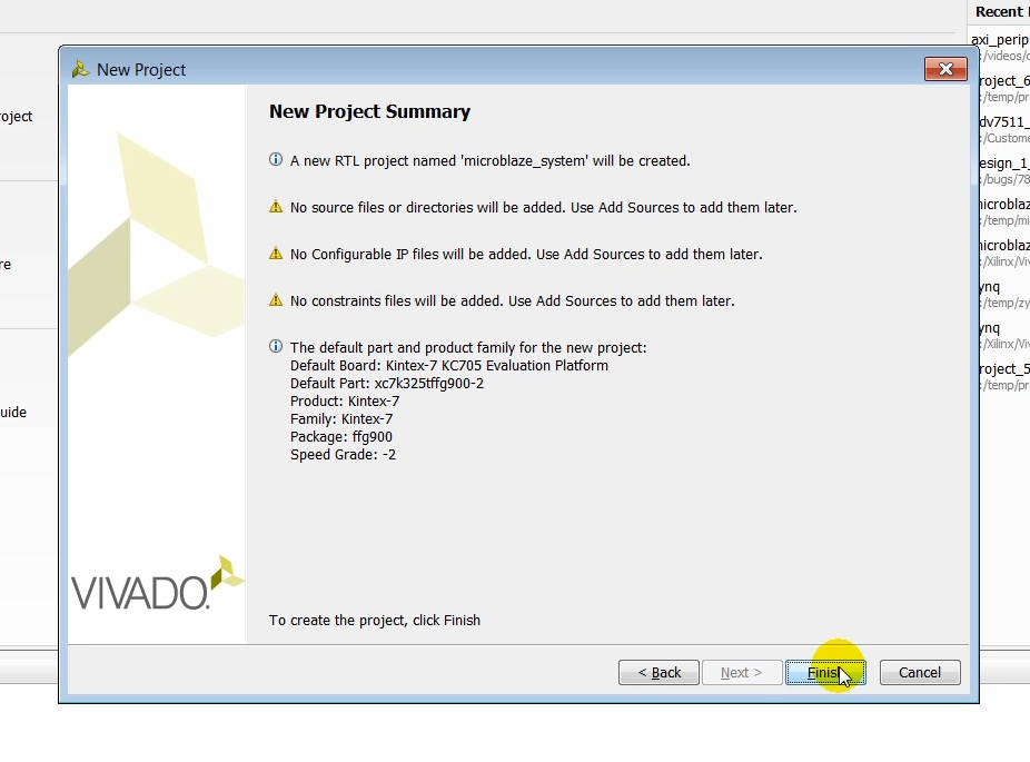
(2:13) Lets review the summary screen to make sure that all the options have been entered correctly and click finish.
Step: click Finish
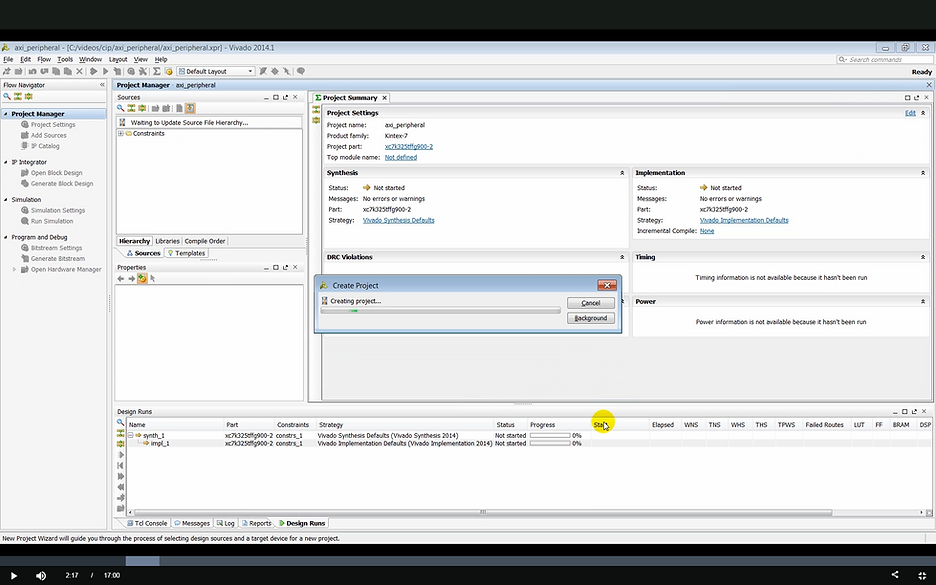
Output: the Create Project status bar pops up
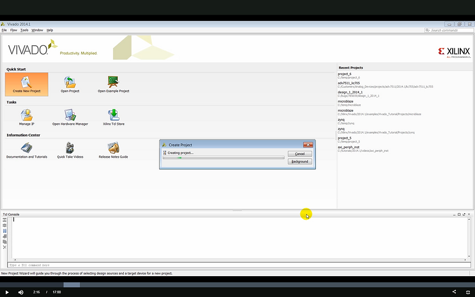
Output: the Create Project pop-up shows Creating project…
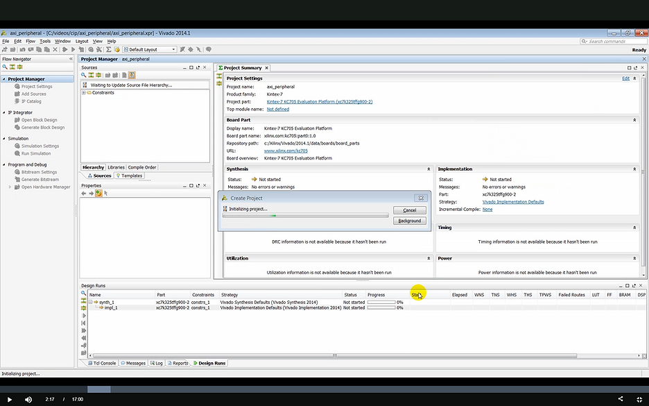
Output: the Create Project pop-up shows: Initializing project…
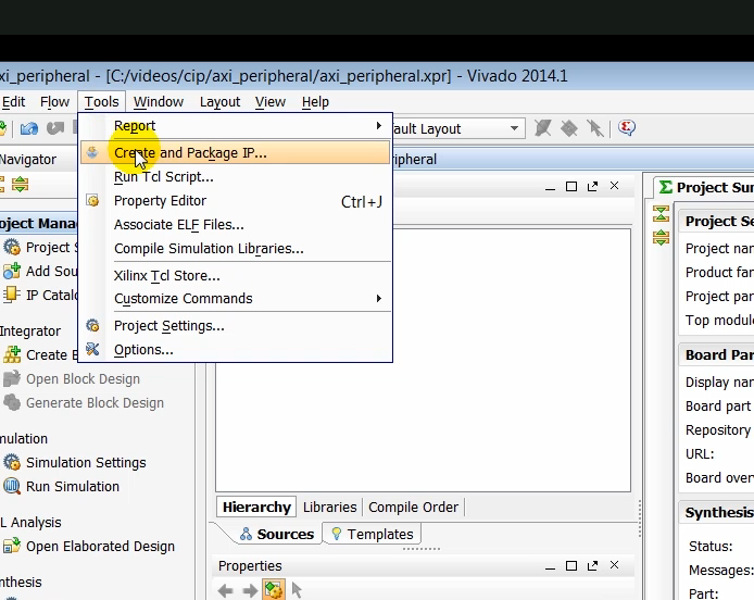
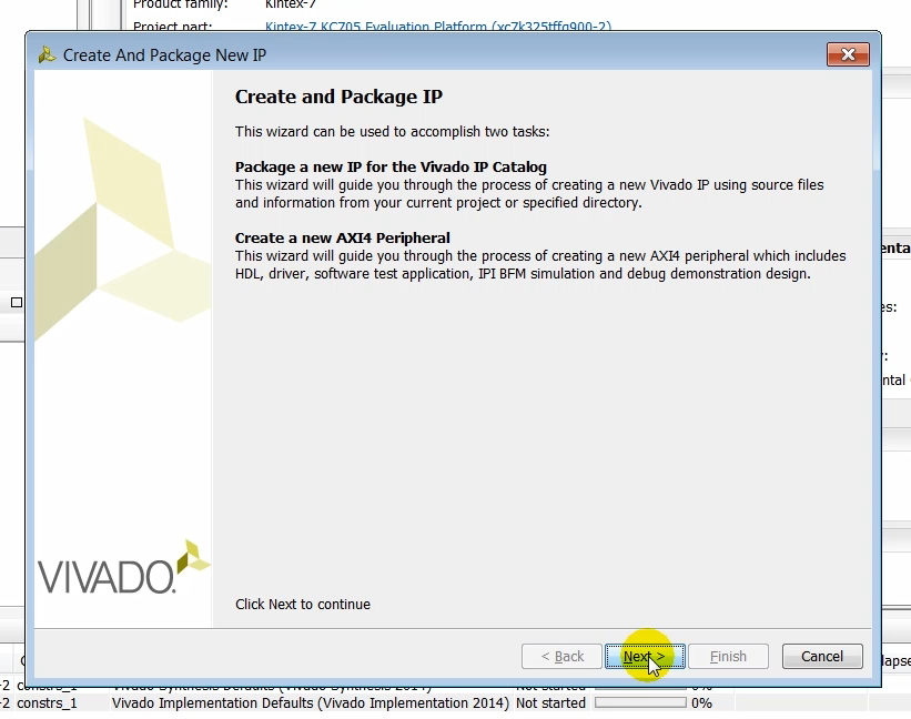
(02:19) Once the project has been created, we launch the create and package IP feature. Using this feature, you can either package a new IP or you can create a custom AXI peripheral to which your logic can then be added to make your own custom IP.
Create and Package IP
Step: click Tools > Create and Package IP…
Step: click Next
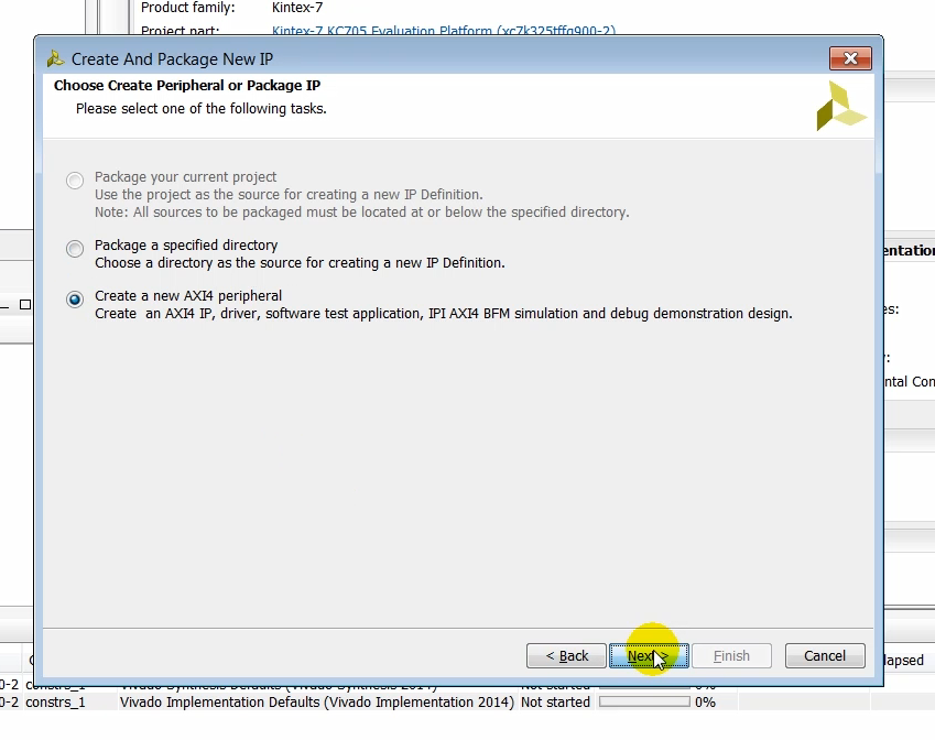
(2:35) When you launch the create an IP package feature in a new project, you have two choices: (1) you either package a preexisting project directory or you can create a new AXI4 peripheral. We choose the creating a new AXI peripheral and click next.
Step: click Create a new AXI4 peripheral
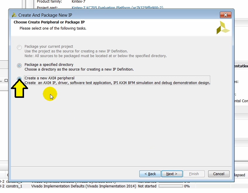
Step: click Next
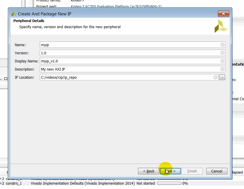
(2:53) In the next page we can specify a several options such as name, version, display name, description, and the location where the IP will be created. Once the IP is created, you can search for the IP in the IP catalog using the name given to this peripheral. Also note down the IP location. This is where the IP repository is created.
Step: click Next
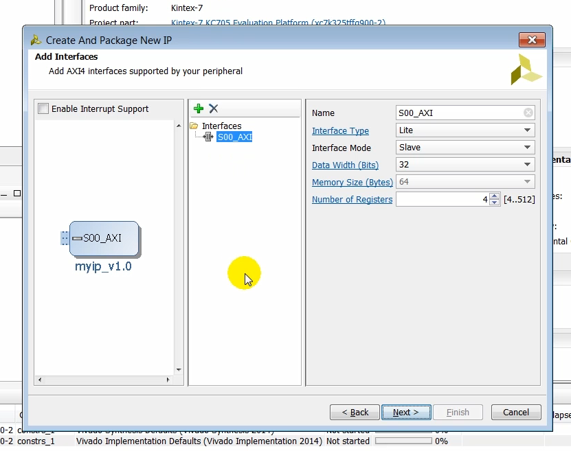
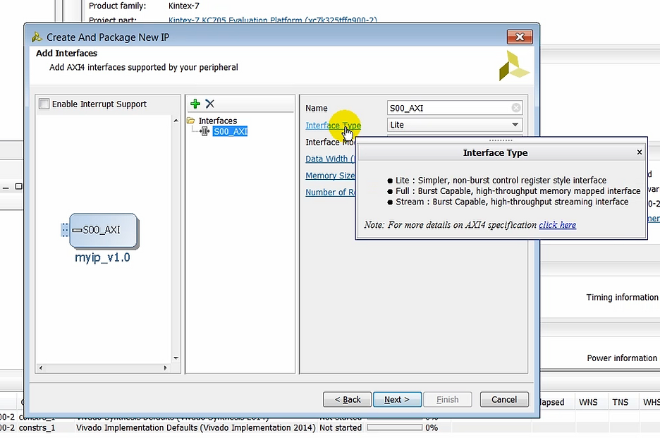
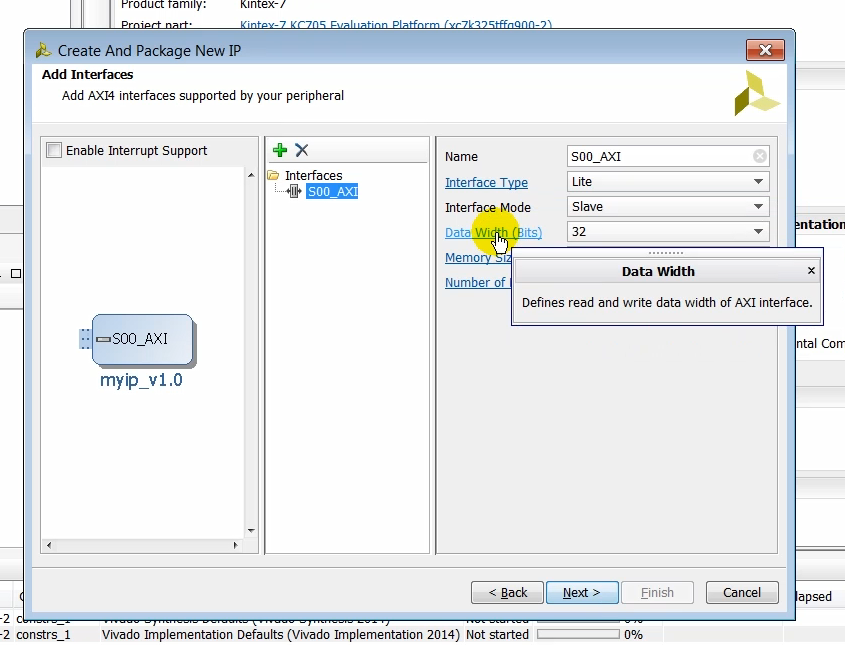
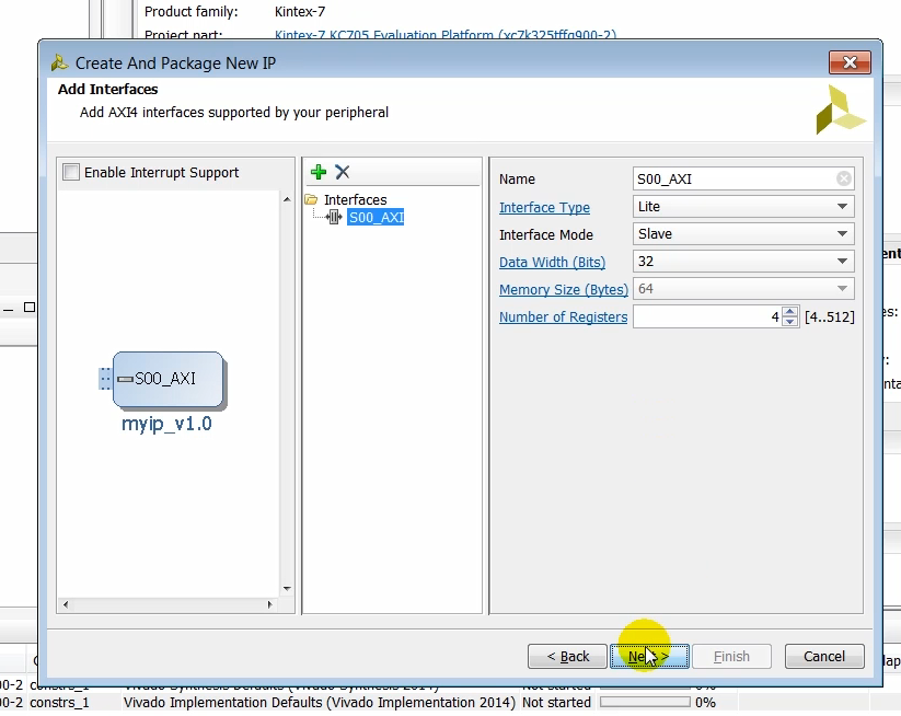
(03:18) On the add interfaces page you choose the number of interfaces that you want the AXI peripheral to have. Interfaces can be added by clicking the plus sign and deleted by selecting the delete icon. Notice that the components symbol also gets updated as you add and delete interfaces. Several properties of the AXI4 peripheral can be specified on this page. You can specify the name of the AXI interface in the name field. You can choose the type of AXI4 protocol desired. The choices are light, full and stream. You can specify whether the interface is created in a master mode or a slave mode. You can also specify the data width for the interface and the number of registers desired. Currently the number of registers supported by this feature for AXI Lite interfaces between 4 to 512. For the purposes of this video, we’ll go with the default values.
Demonstration of How to Add and Remove an AXI Interface (Not Required for These Steps)
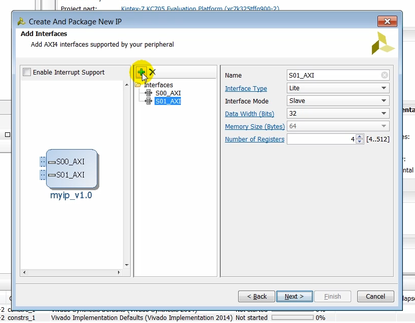
Step: click + to add an interface
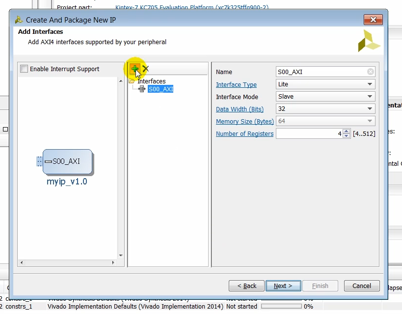
Output: a new AXI slave interface pops up after clicking +
Step: click X to remove an interface
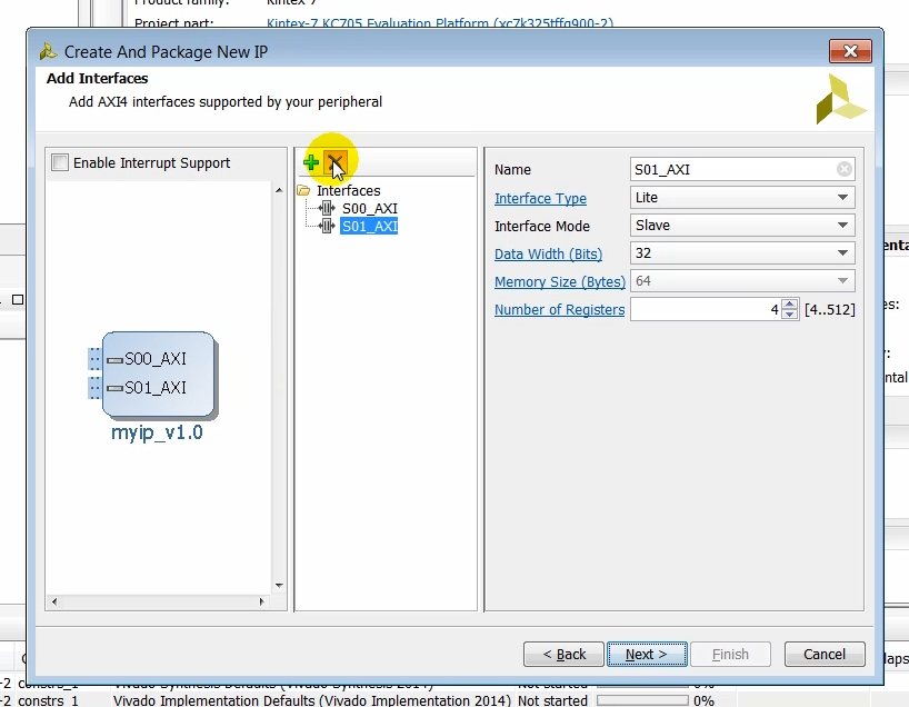
Output: the new interface disappears after clicking the X to remove an interface
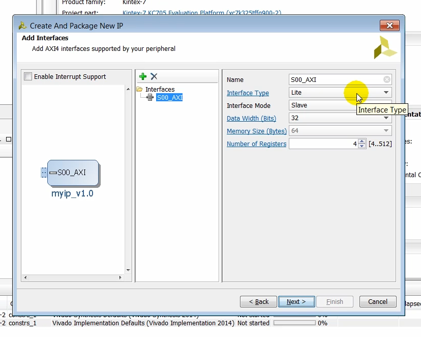
Output: pop up tool-tip text on Interface Type
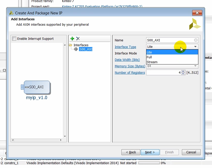
Output: the Interface Type options: Lite, Full and Stream
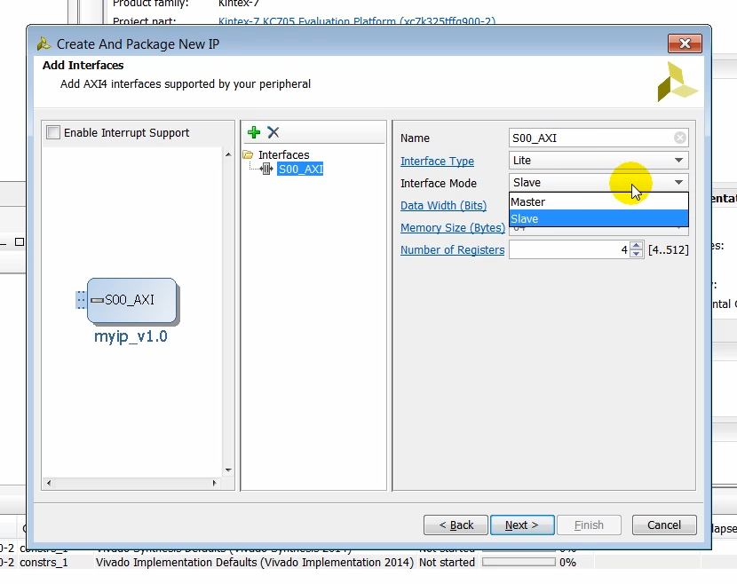
Output: the Interface Mode options: Master and Slave
Output: the tool-tip text of Interface Type:
-
Lite : Simple, non-burst control register style interface
-
Full : Burst Capable, high-throughput memory mapped interface
-
Stream: Burst Capable, high-throughput streaming interface
Note: For more details on the AXI4 specification click here (TBD get link)
Output: the tool-tip text of Data Width (Bits)
(4:09) Click next to get to the by summary page…
Continue Creating and Packaging a New AXI Peripheral
Step: click Next
(4:10) …where you can either add the IP to the repository or edit the IP further to create a custom IP. You can also create a test-bench to verify the AXI4 peripheral using an AXI bus functional simulation model or you can test the IP in hardware by using the JTAG-to-AXI IP core. In this case we will select the verify peripheral IP using AXI4 BFM simulation interface option…
Output: the default create a customer IP screen pops up
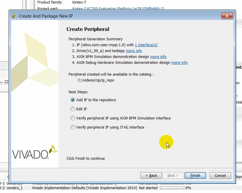
Step: click Verify peripheral IP using AXI4 BFM Simulation interface
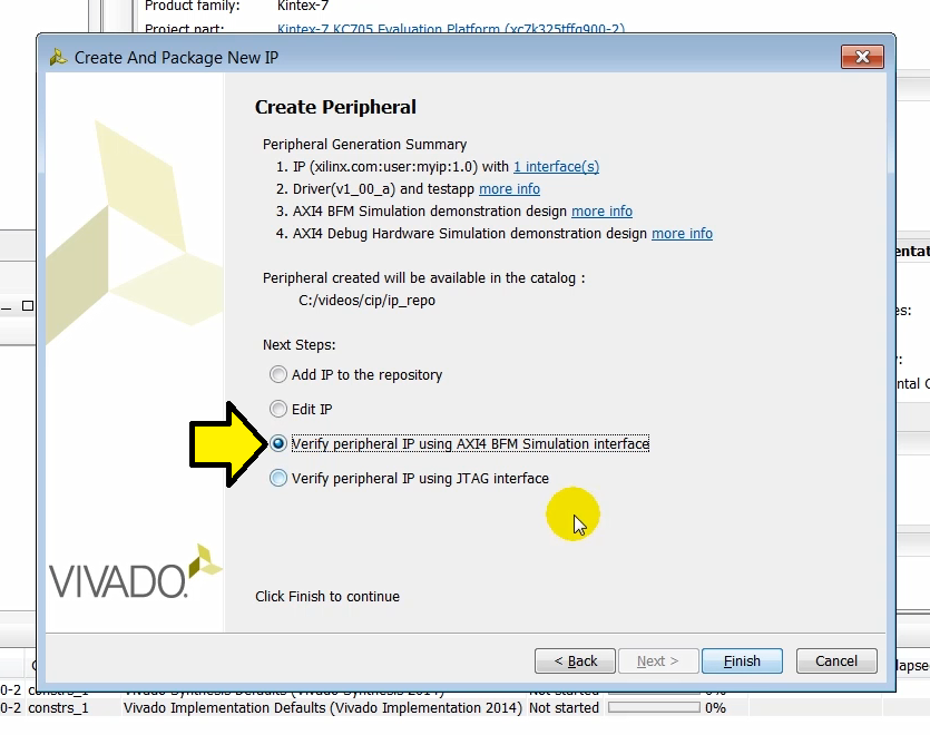
(4:32) …and click on finish to create the AXI peripheral.
Step: click Finish
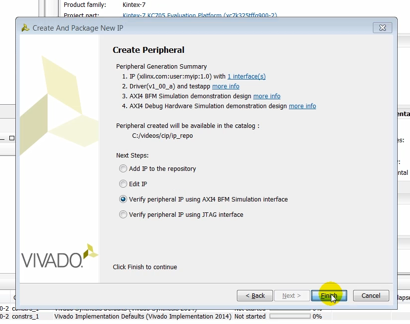
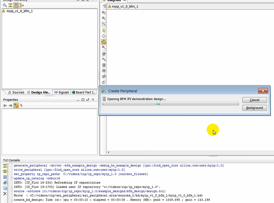
Output: a Creating new peripheral… window pops up
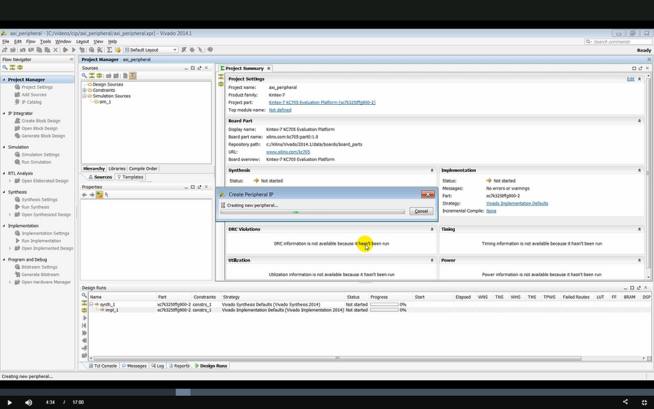
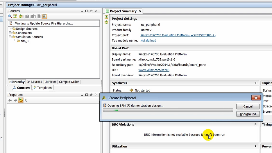
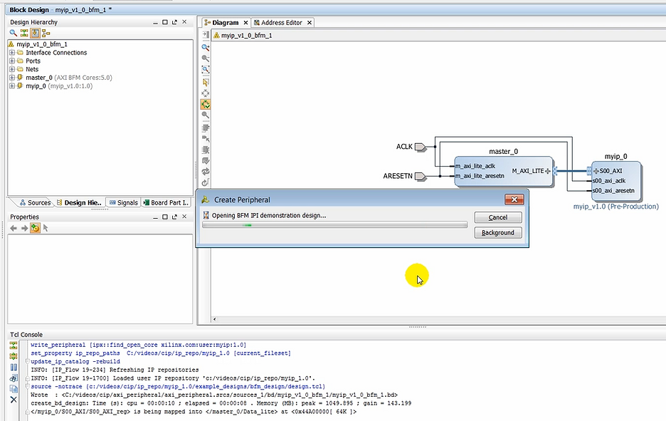
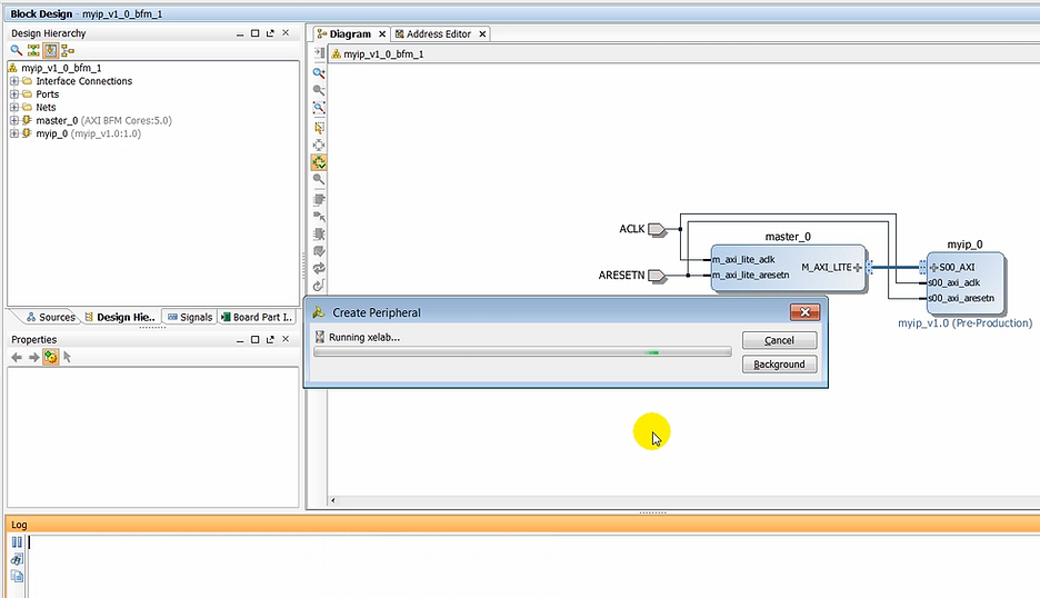
(04:34) As you notice, a block design is created and an AXI peripheral is instantiated unconnected to the AXI bus functional model.
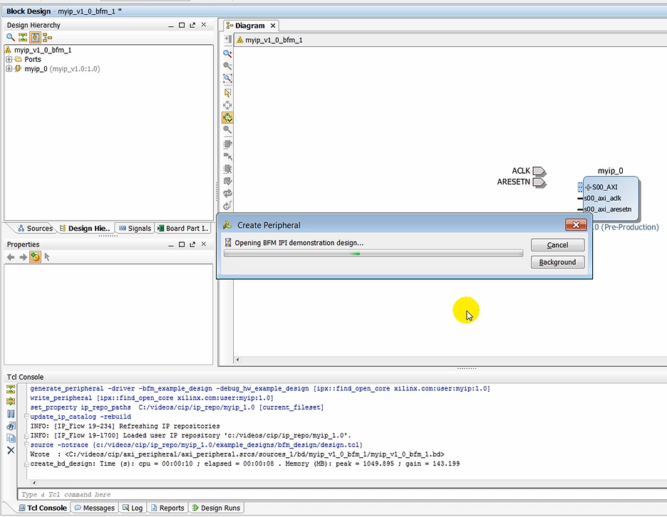
Output: a Opening BFM IPI demonstration design… status window pops up
Output: create_bd_design output on the Tcl Console
Output: the diagram starts to populate, ACLK, ARESETN and myip_0 are added
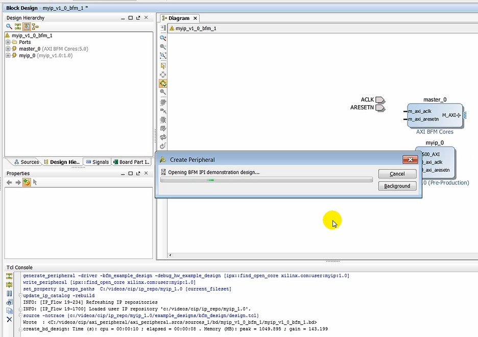
Output: the diagram continues to populate, master_0 is added
Output: ACLK is connected to m_axi_lite_aclk & s00_axi_aclk and ARESETN is connected to s00_axi_aresetn & m_axi_lite_aresetn
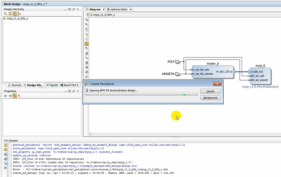
Output: additional Tcl Console output about /myip_0/S00_AXI/S00_AXI_reg being mapped into /master_0/Data_lite at 0x44A00000
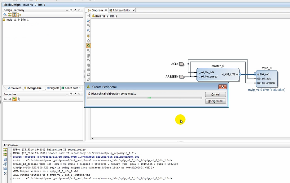
Output: additional Tcl Console about VHDL and bd file for the BFM being written out.
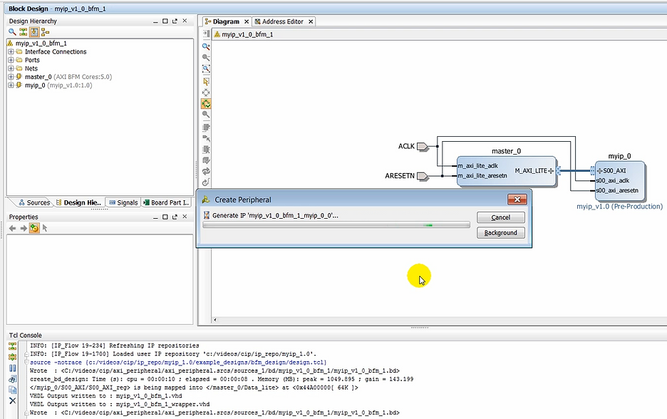
Output: Create Peripheral pop-up reports: Generate IP ‘myip_v1_0_bfm_1_myip_0_0’…
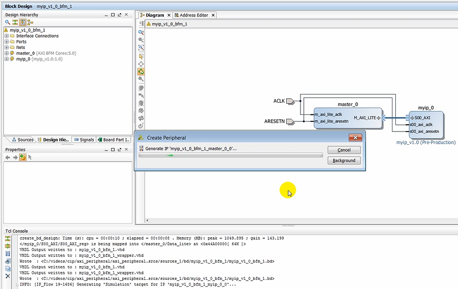
Output: Create Peripheral pop-up reports: Generate IP ‘myip_v1_0_bfm_1_master_0_0’…
Output: Create Peripheral pop-up reports: Running xelab… (note: xelab is the simulator compiler. See [UG900] p.120 for more info)
Output: Create Peripheral pop-up reports: Launching simulation for ‘myip_v1_0_tb_behav’…
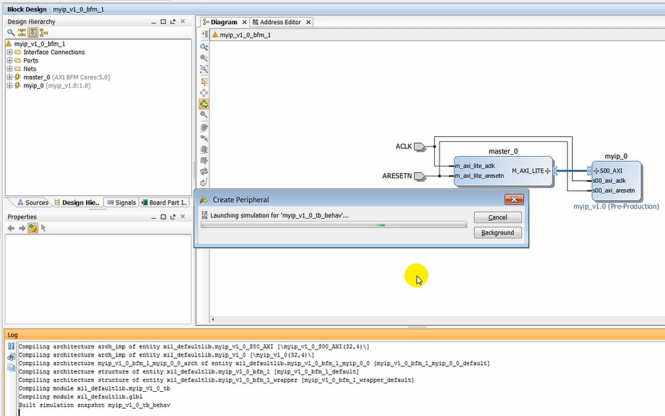
Output: xsim starts to run
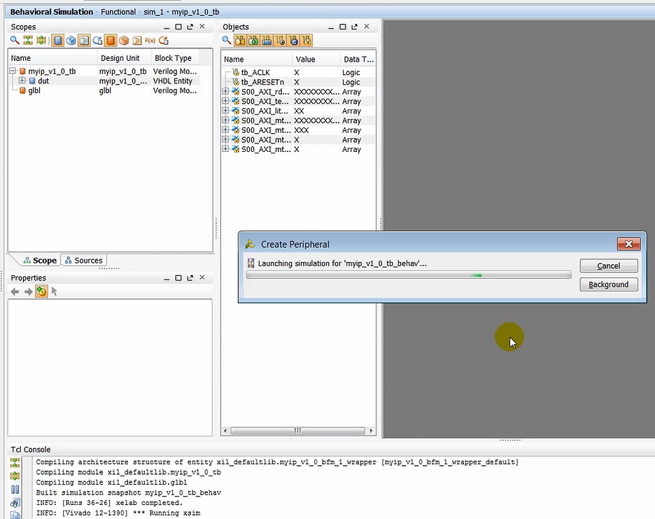
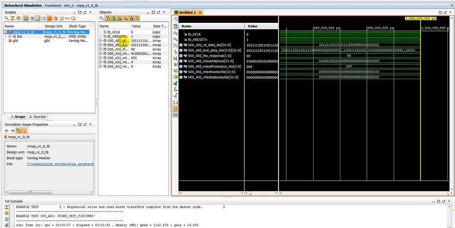
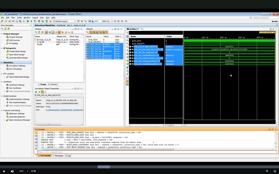
(05:01) The design is then elaborated and simulation is launched. The test-bench that is created with this design, exercises the bus functional model (BFM) to generate several read and write transactions. Those transactions can then be verified in the simulation window as well as on the Tcl console where the result of read/write transactions are written out.
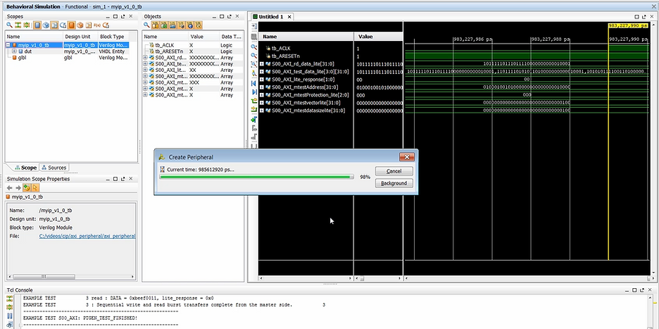
Output: xsim running, current time reported.
Output: xsim done
How to Format Objects as Hex
Demo step: click a bus in the Objects window
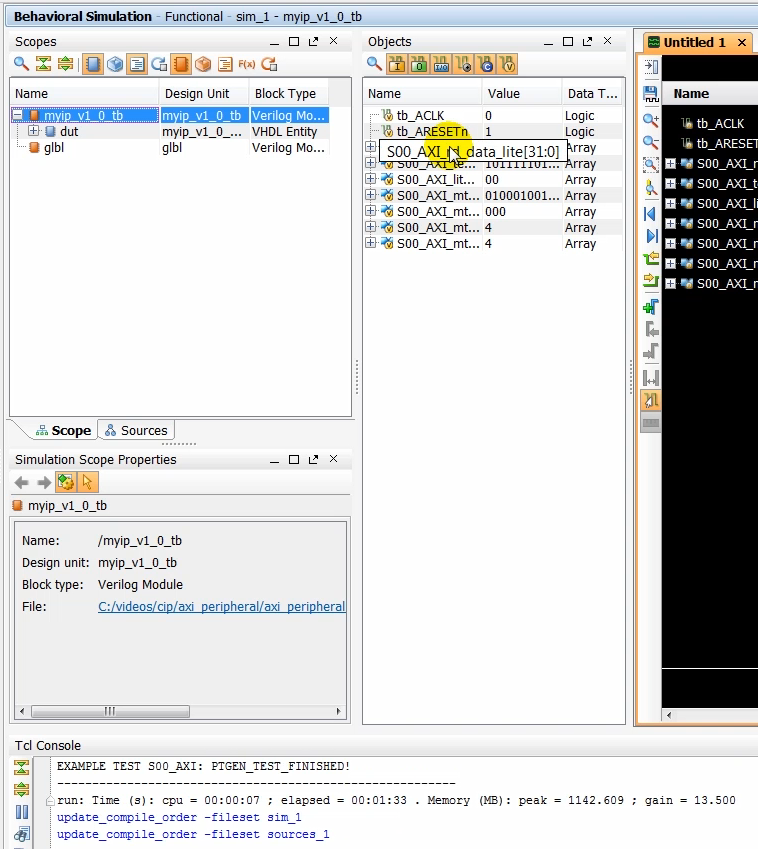
Demo step: click Radix, Hexadecimal
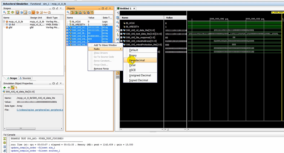
Output: see the hex values in the Objects window
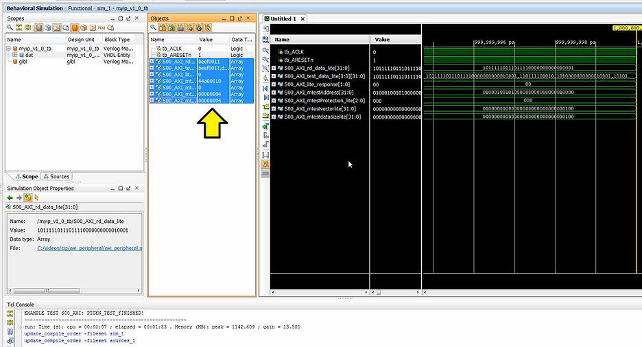
(5:23) Take a moment to look at the waveform window and also the TCL console to verify that write and read operations took place alright.
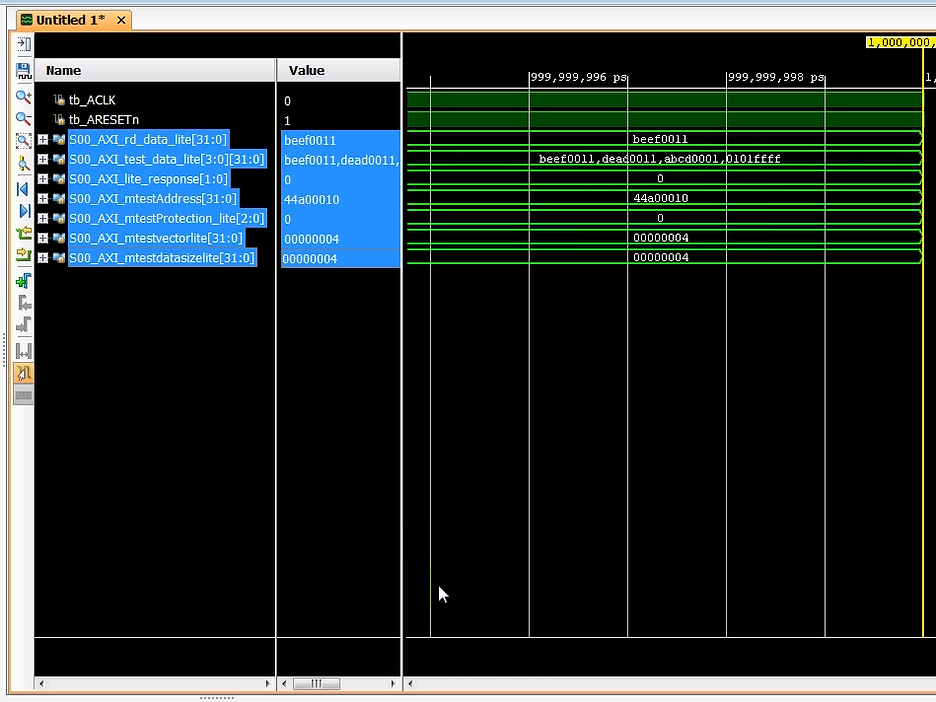
How to Format Signals as Hex
Step: select signals > select Radix > select Hexadecimal
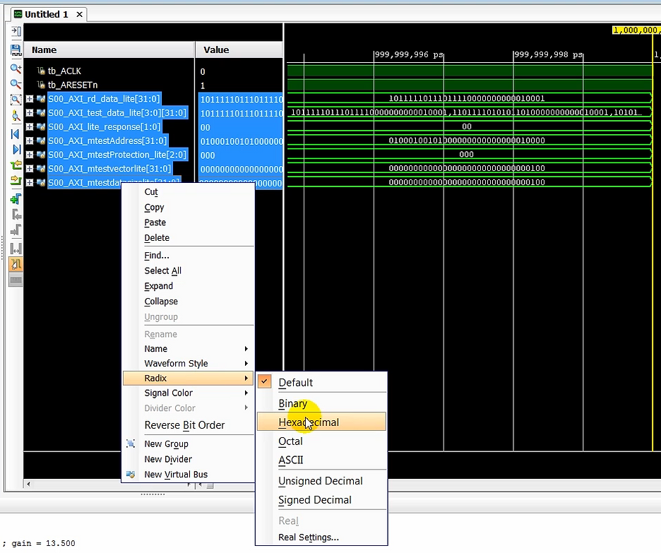
Output: signals in hex
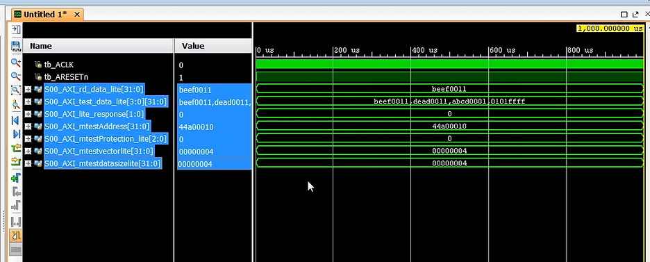
How to Zoom Fit
Step: TBD
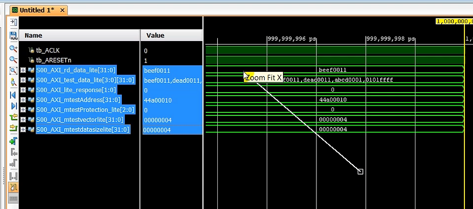
Output: zoomed version
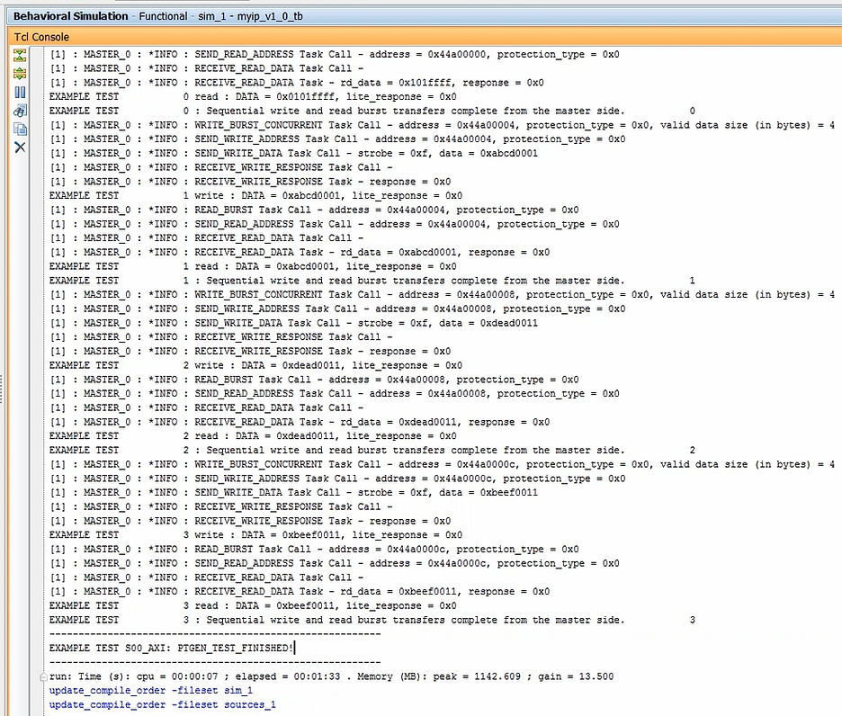
(5:35) You will notice several statements in the Tcl console showing the data written to the peripheral and the data read out from it.
Output: the Tcl console data
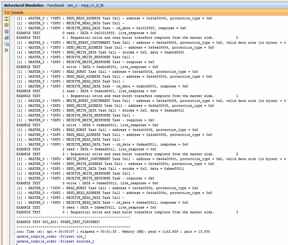
Output: start of the Tcl console data
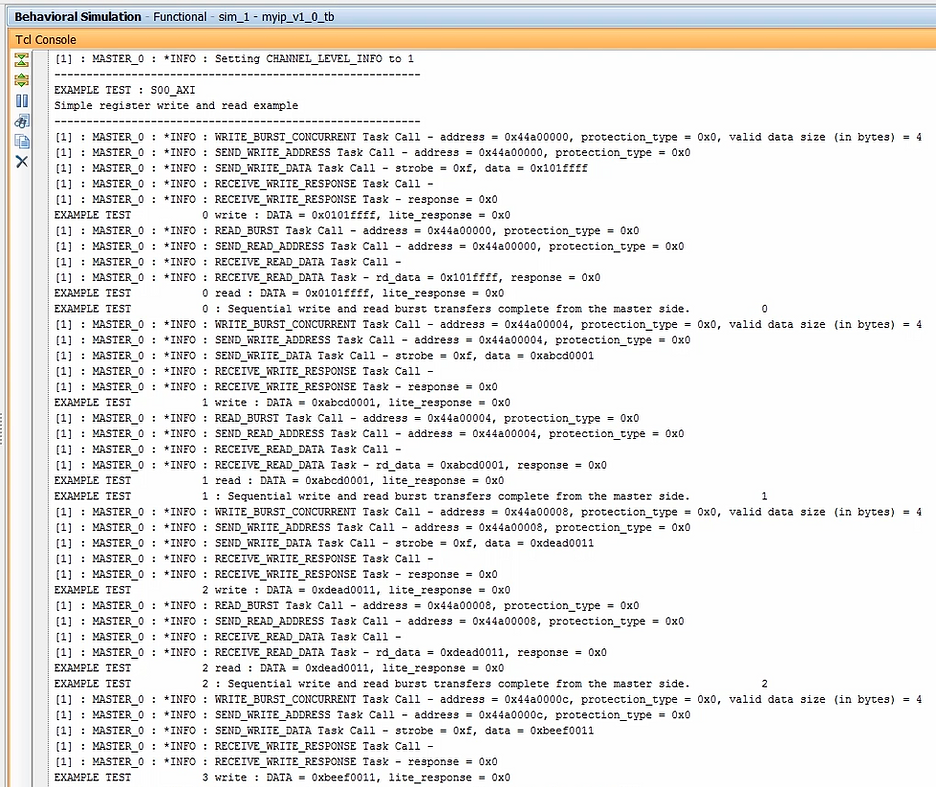
Output: end of the Tcl console data
(05:44) If adding custom logic to this peripheral is desired, you can add your custom logic to this peripheral at this time. The peripheral can then be repackaged to turn it into a custom IP.
Step: add custom logic: TBD
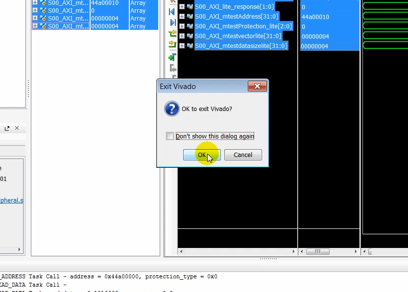
(6:00) At this point we can close the simulation and exit Project. Click okay to exit from Vivado.
How to Exit Vivado
Step: Click File > Exit
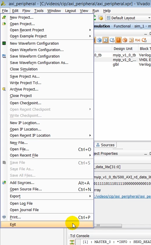
Step: click OK to complete exiting Vivado
Create a MicroBlaze system in Vivado and Connect our Custom AXI Peripheral
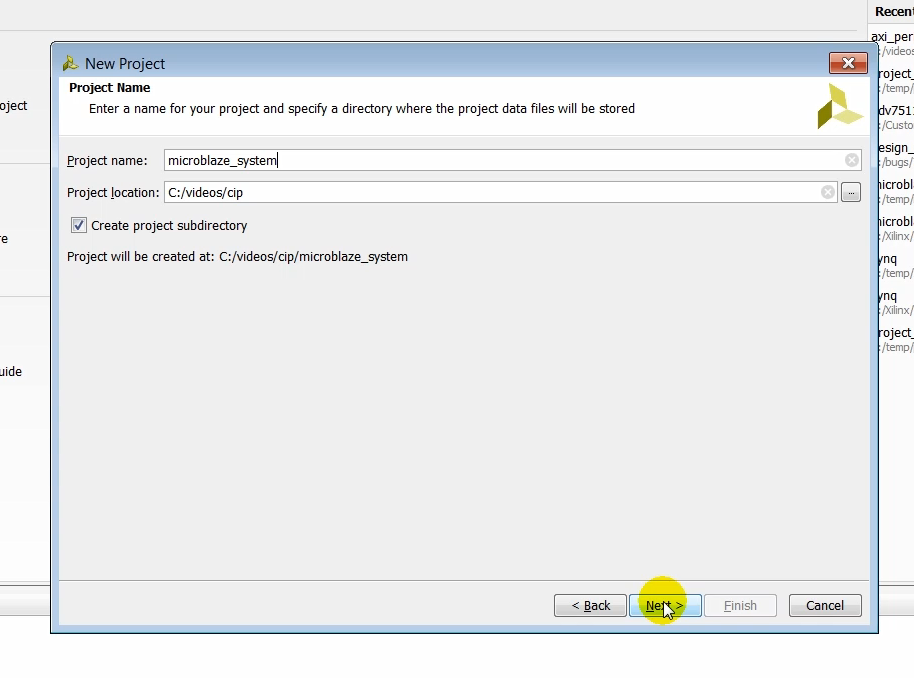
(6:18) Next one we’ll create a new Vivado project to create a MicroBlaze based system in which we will instantiate the AXI peripheral that we just created. Again, like before we’ll create a Vivado project using the default settings and making sure that we target it to the KC705 board.
Step: click Create New Project
Click Next
Step: enter microblaze_system as the Project name: and click Next
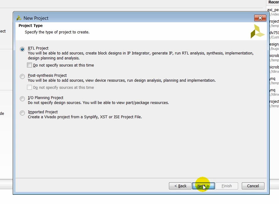
Step: leave RTL Project selected and click Next
Step: click Next
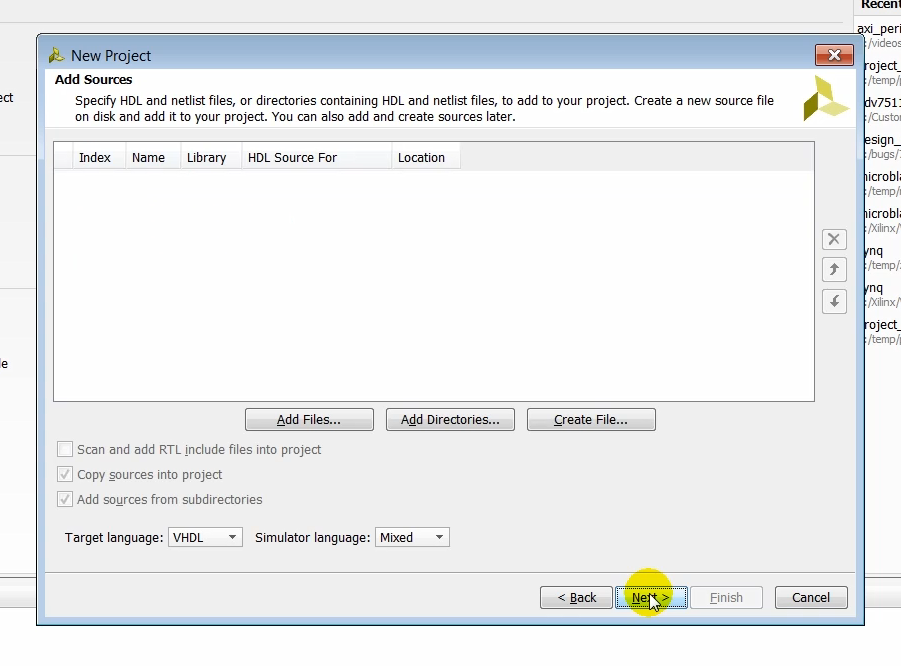
Step: click Next
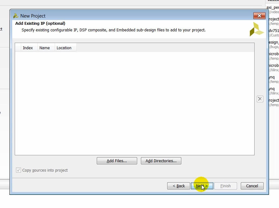
Step: click Next
Step: click Boards
Step: click Kintex-7 KC705 Evaluation Platform
Step: click Next
(06:54) Take a moment to review the new project summary page to ensure that all the products settings have been entered correctly and click finish.
Step: after review, click Next
Output: a Create Project status window pops up
Output: the Create Project window displays Initializing project
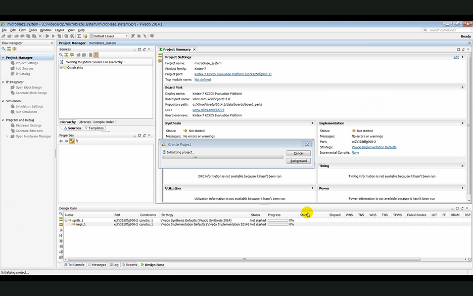
(7:08) Once the projects created we need to create a block design.
Create an IP Integrator Block Design
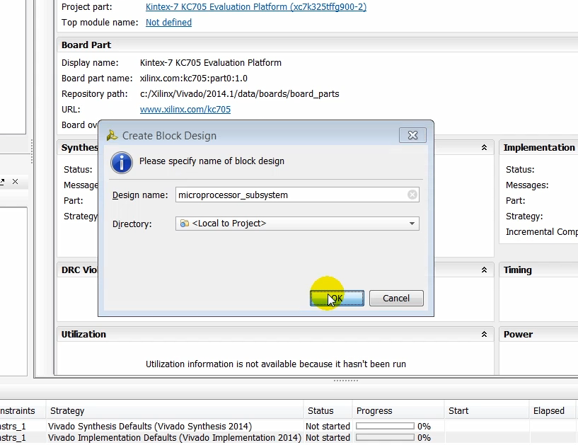
Step: click Create Block Design
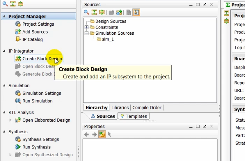
(7:13) We give a name to the block design and click okay.
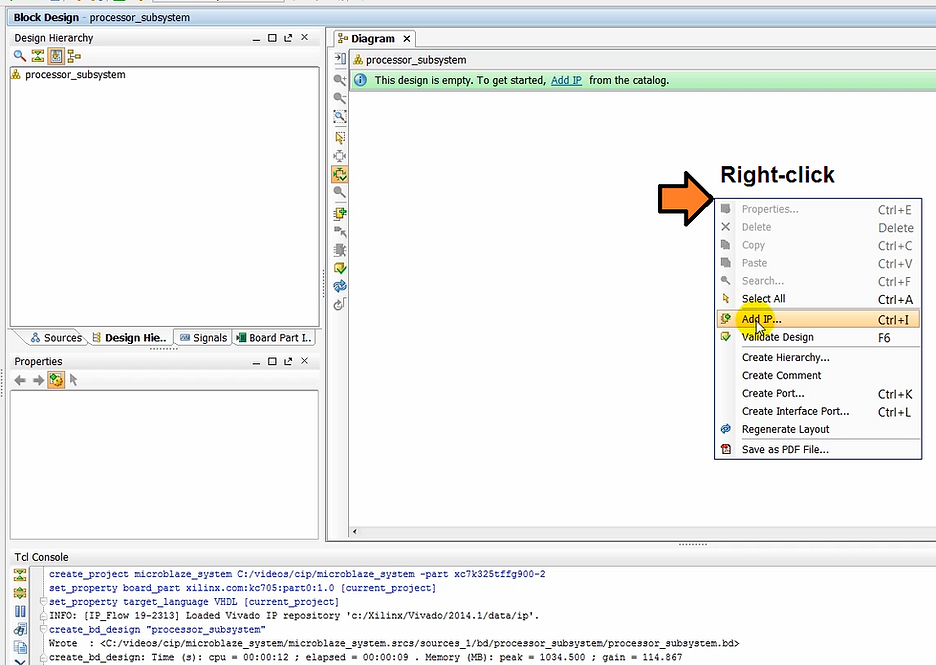
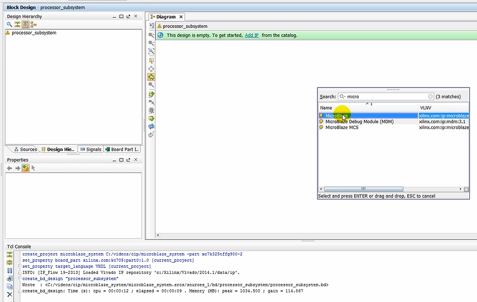
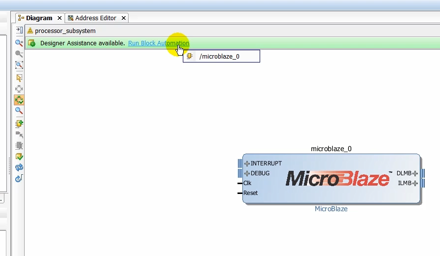
(7:34) In the block design canvas we instantiate a MicroBlaze processor.
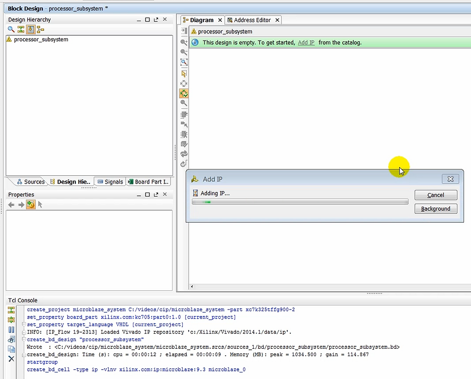
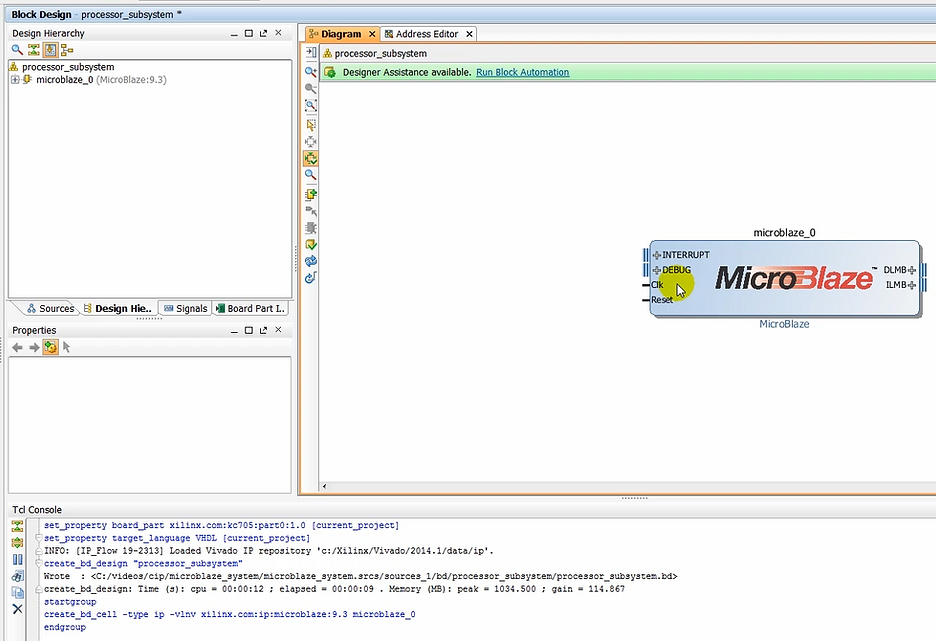
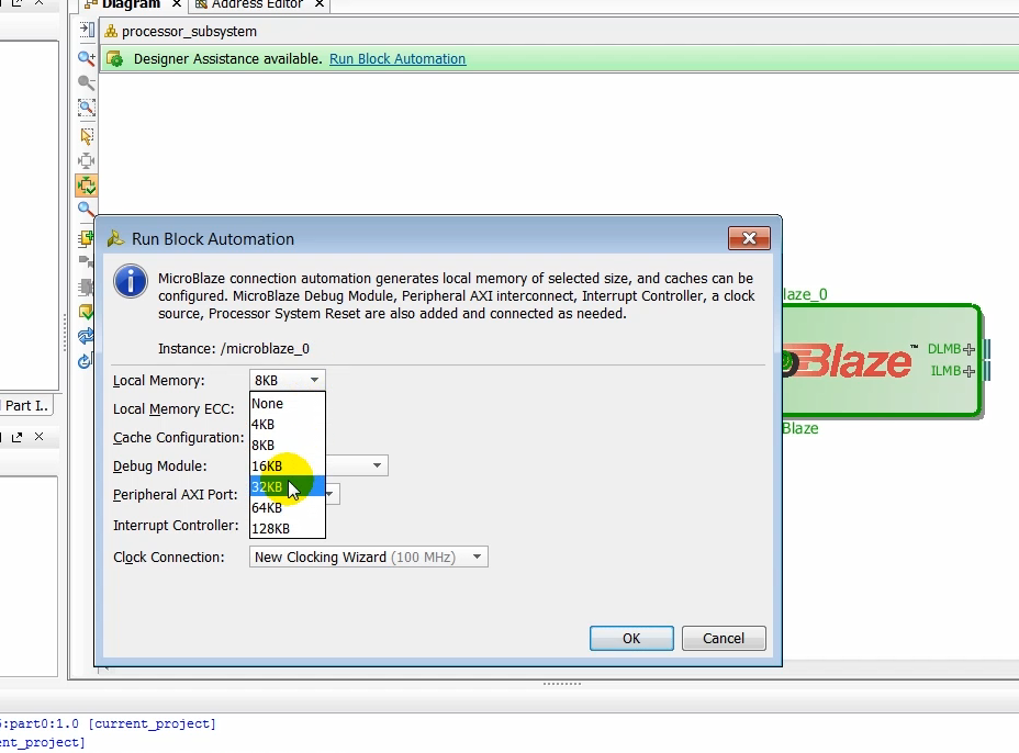
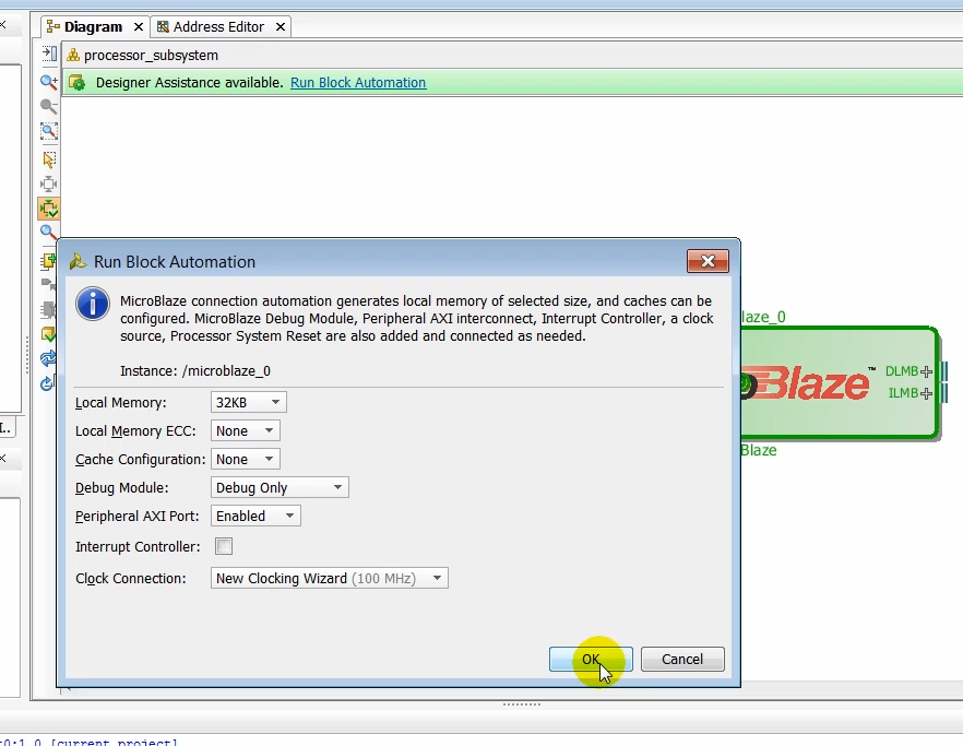
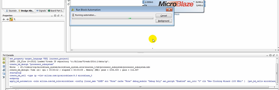
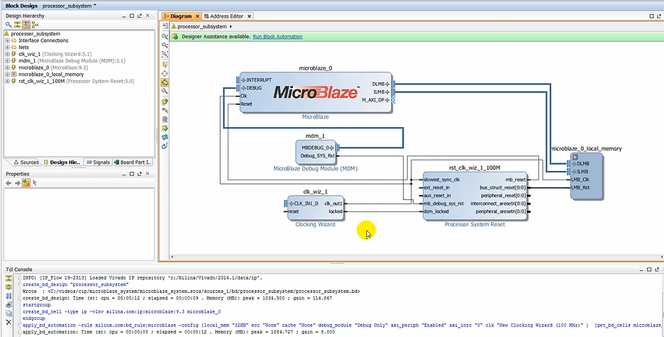
(7:49) Notice that as the processor is instantiated in the design canvas designers assistance becomes available to us. Click on the link to use the block automation. In the run block automation dialogue box we’ll increase the depth of the memory to 32 kilobyte and let all the other remaining options to their default value.
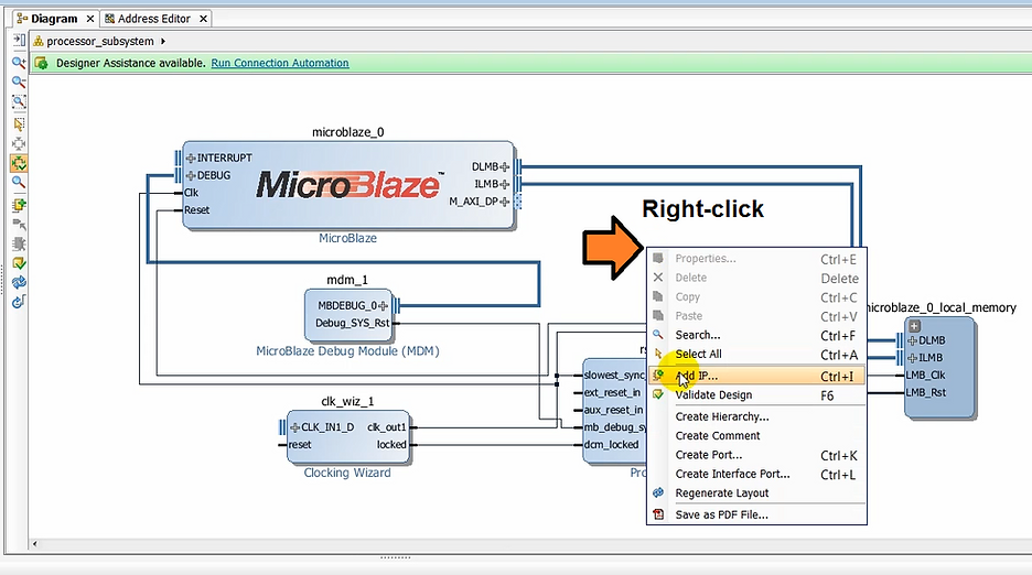
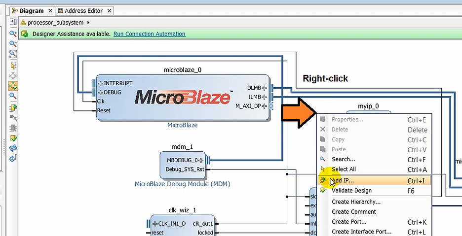
(08:17) Once the basic subsystem is created, we can instantiate the AXI4 peripheral that we had created earlier.
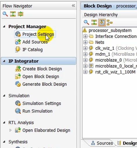
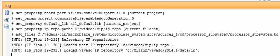
(8:22) To make the AXI peripheral available in the IP catalog, we need to add the repository containing this IP to the Vivado project. We do this by clicking on project settings under project manager and then selecting the IP icon in the left panel.
Make our Customer Peripheral Available
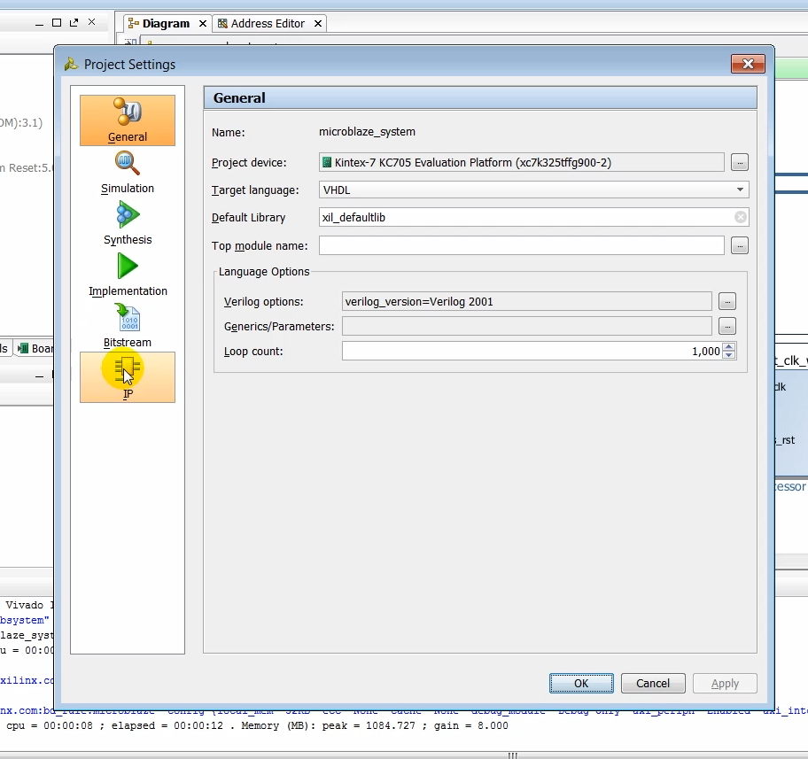
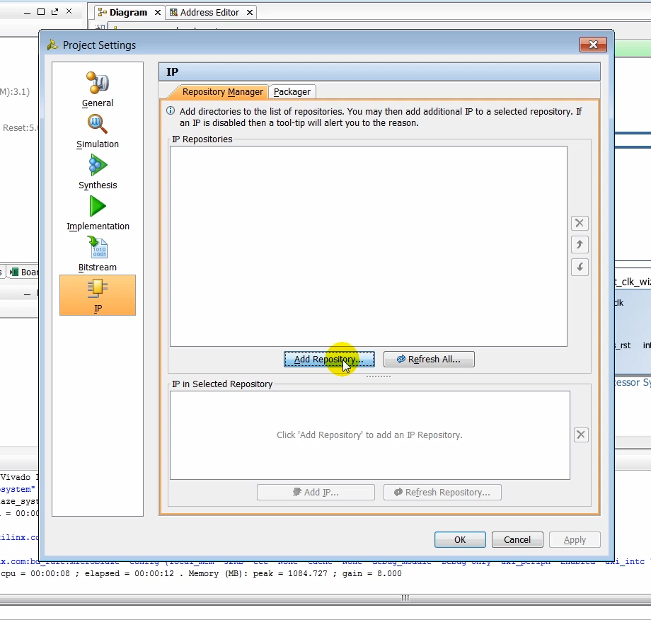
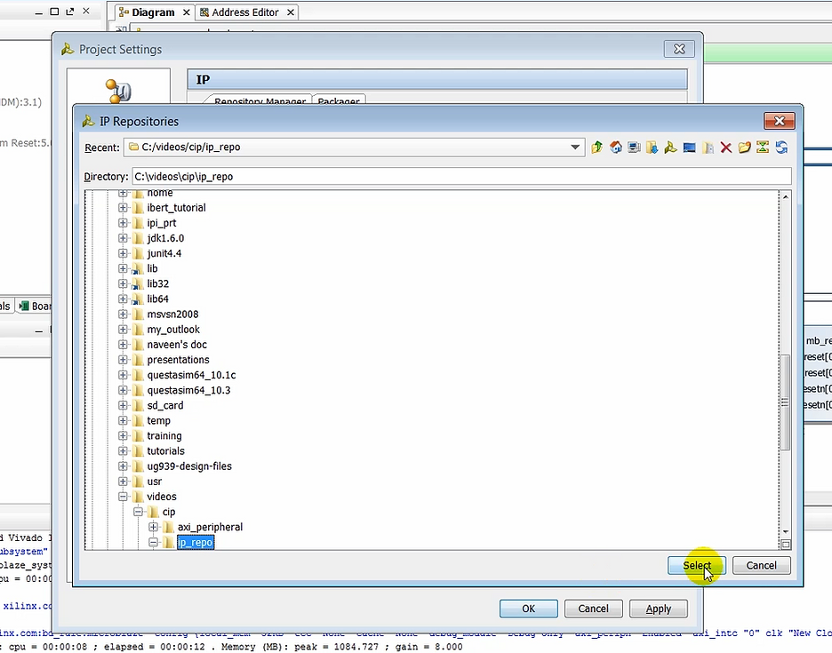
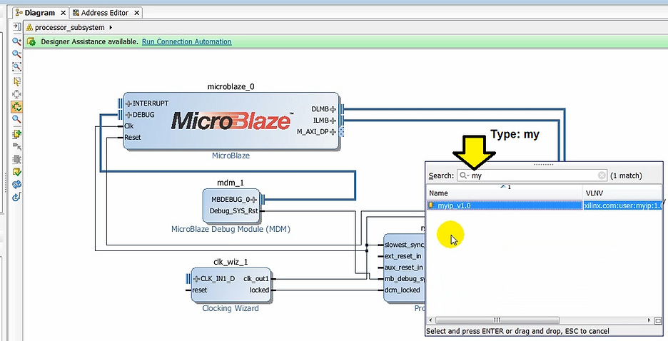
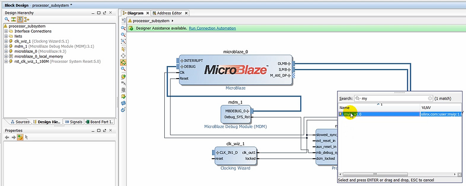
(8:37) Click on IP repository and then browse to the repository called IP repo and click select.
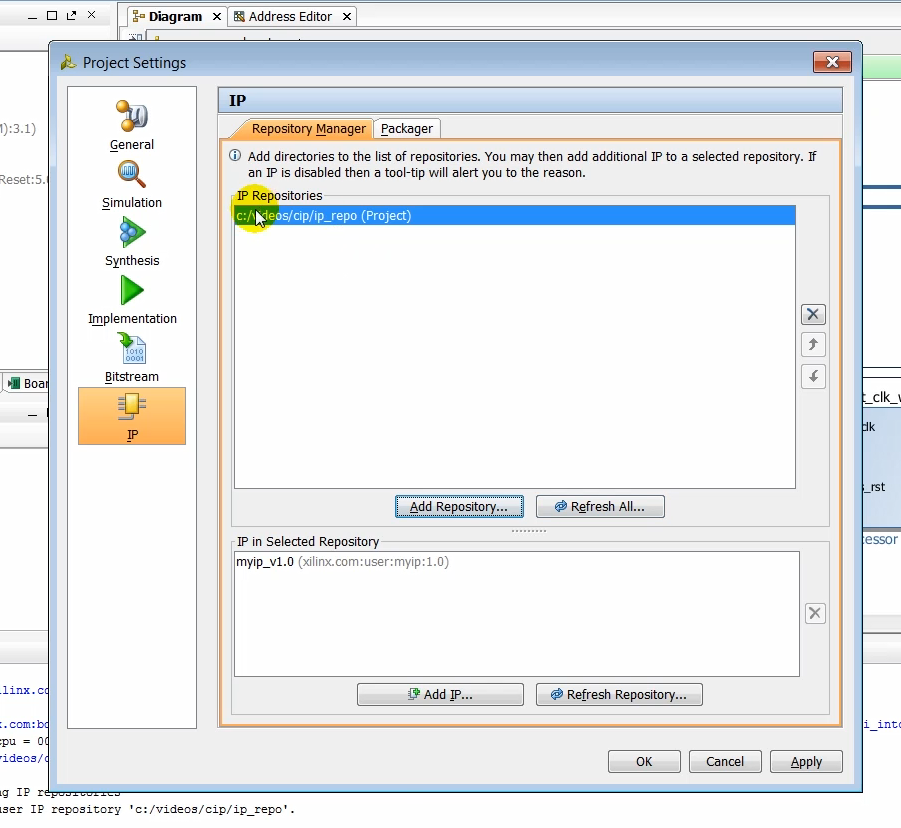
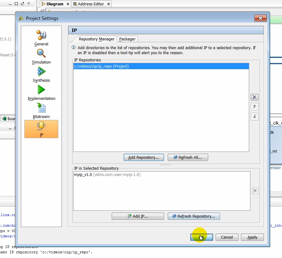
(8:42) As soon as the IP repository is added to the project, you can see the AXI peripherial called myip that was created earlier.
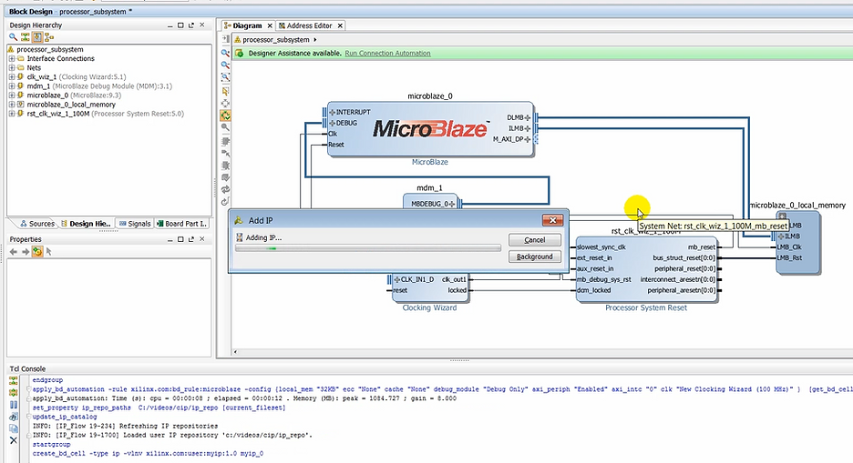
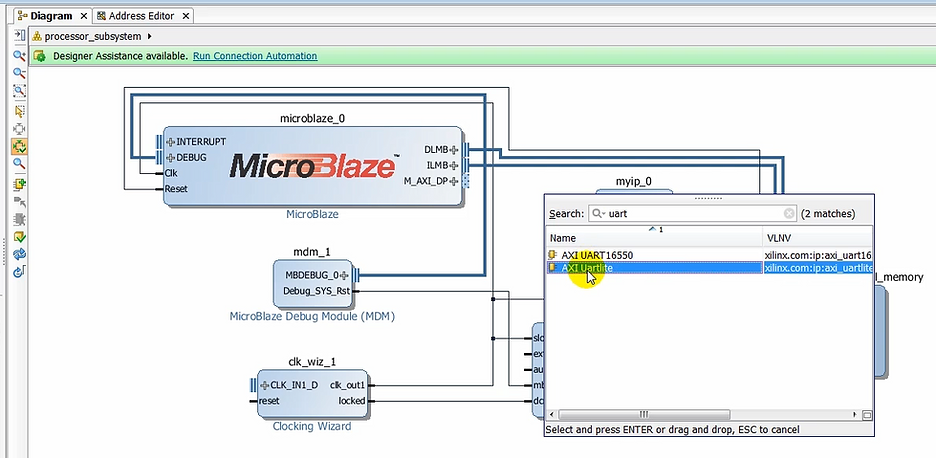
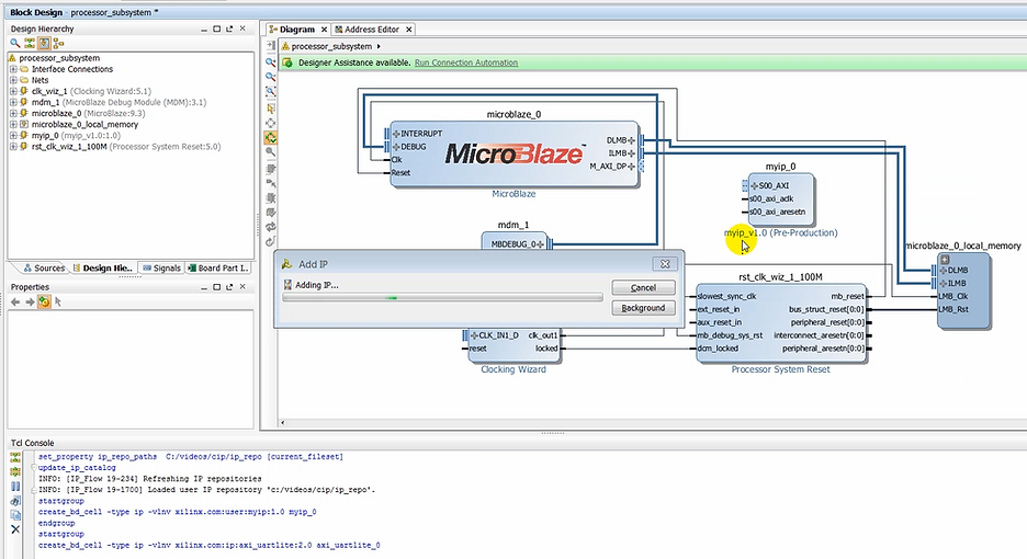
(08:54) Let’s instantiate this IP now along with a UART Lite IP in the design. The UART Lite is the accessory to monitor communication between the hardware and software in the terminal window in SDK.
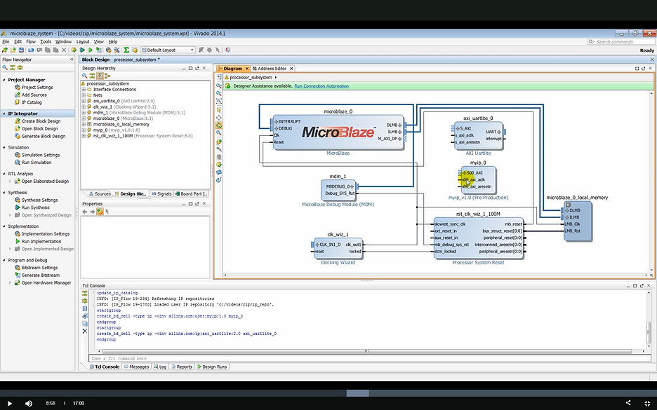
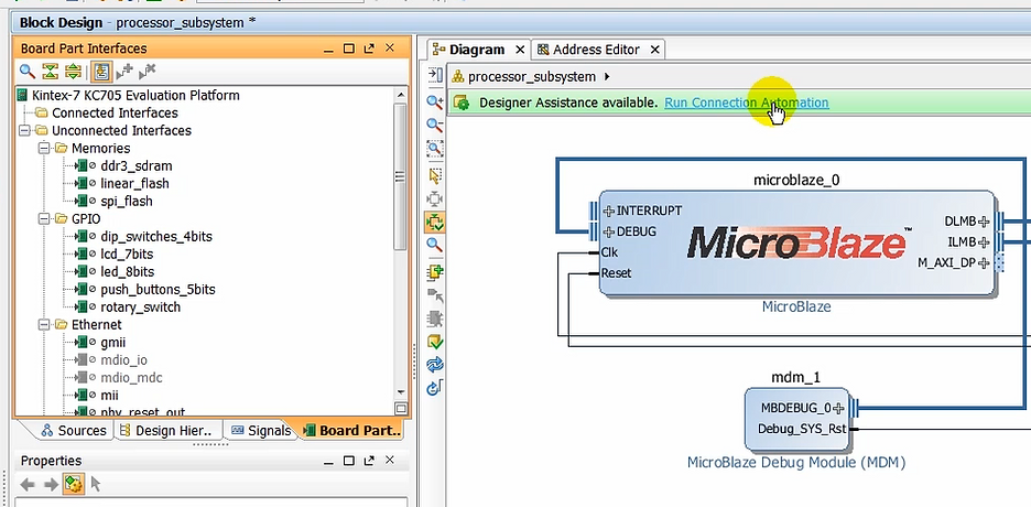
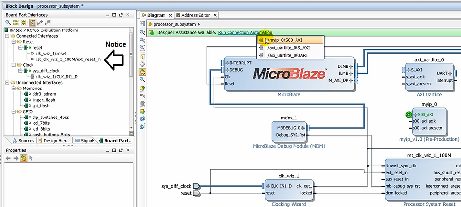
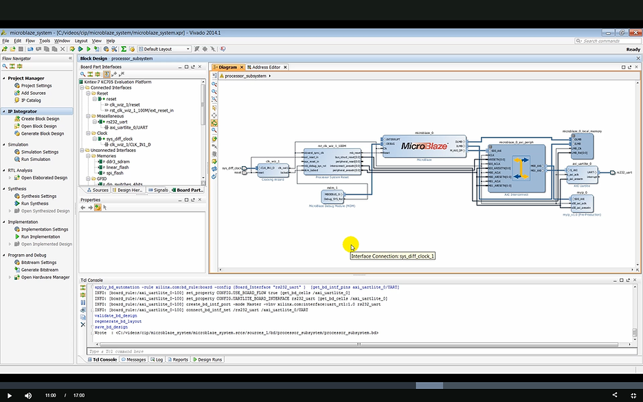
(9:06) You will notice that designers assistance is available again, which we can use to make quick connections of the newly instantiated IP to the MicroBlaze subsystem. I mentioned earlier Vivado is board aware and knows the interfaces present on the KC705 board.
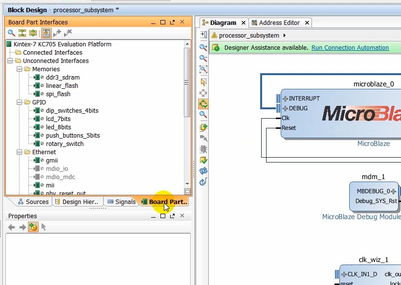
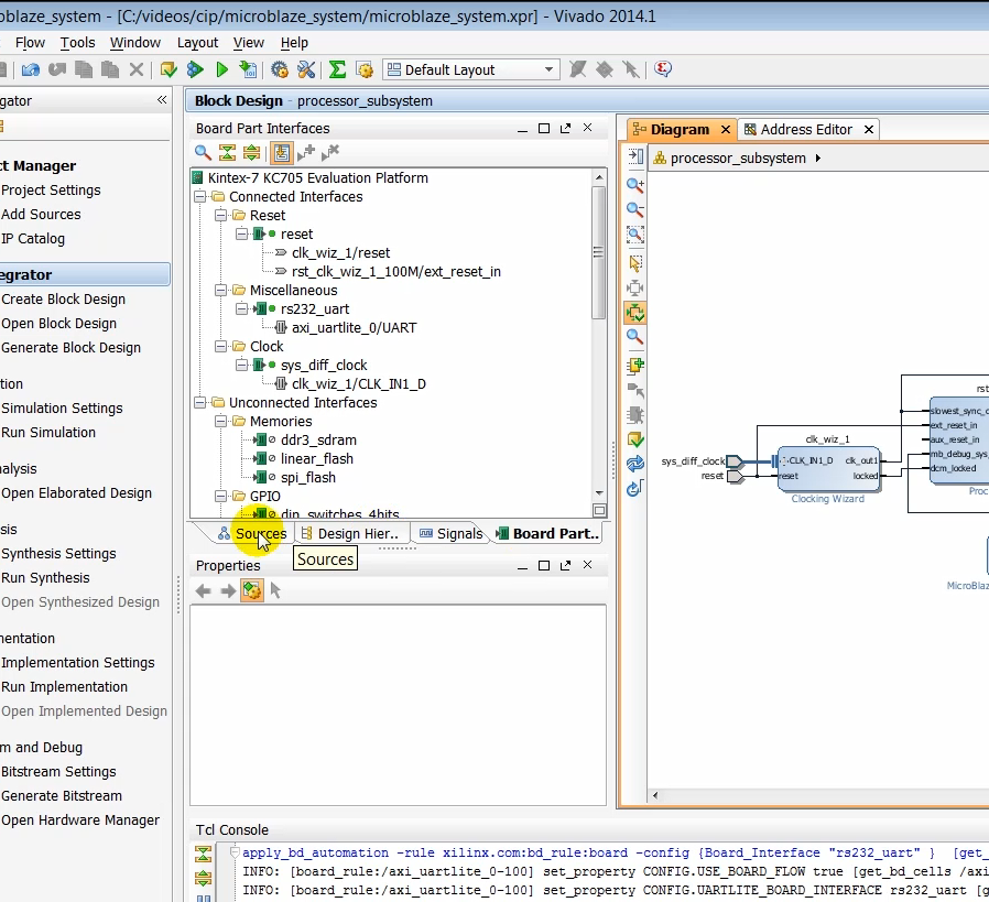
(9:23) As we use designers assistance to make connection to the different interfaces on the board, you will notice that the interfaces that are using the design show up in the connected interfaces folder in the board interface window.
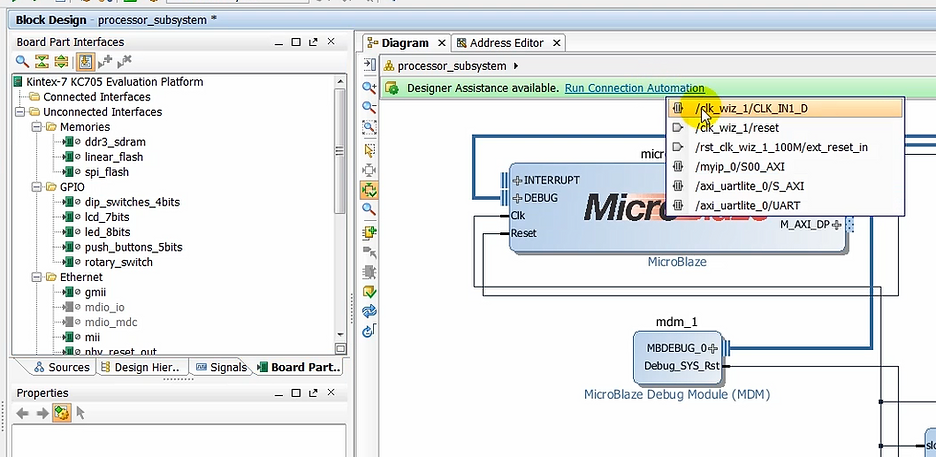
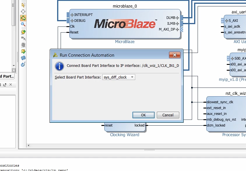
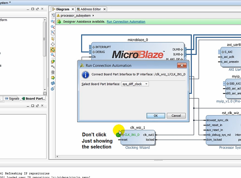
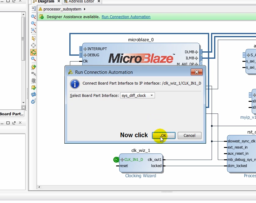
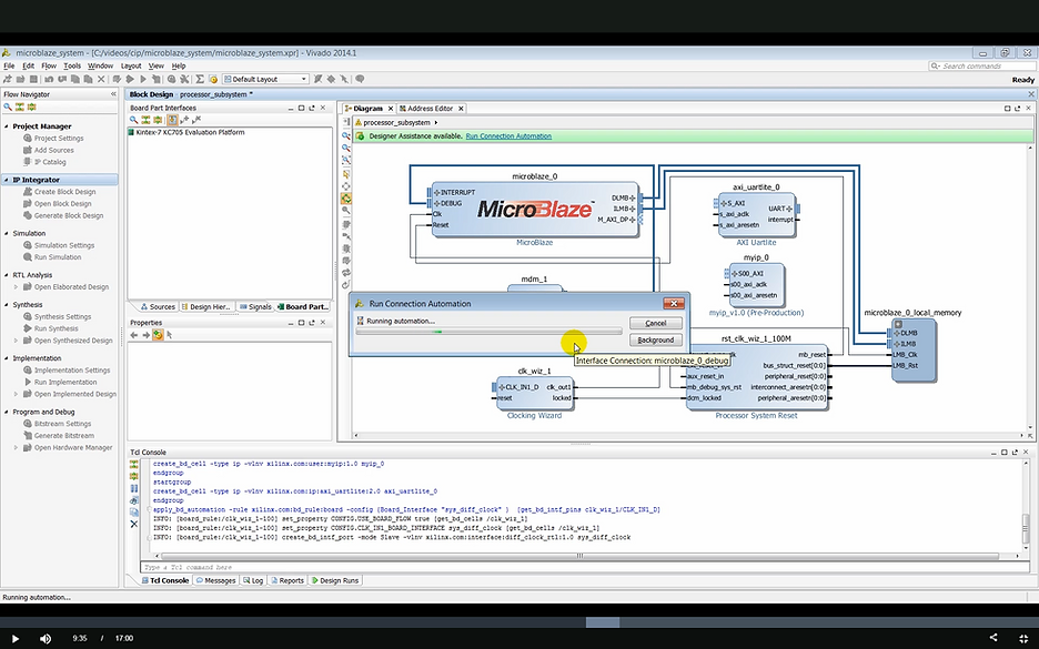
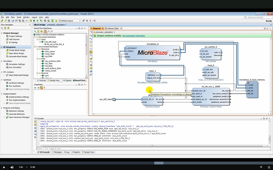
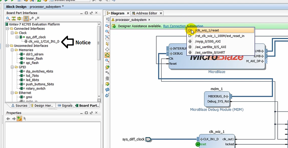
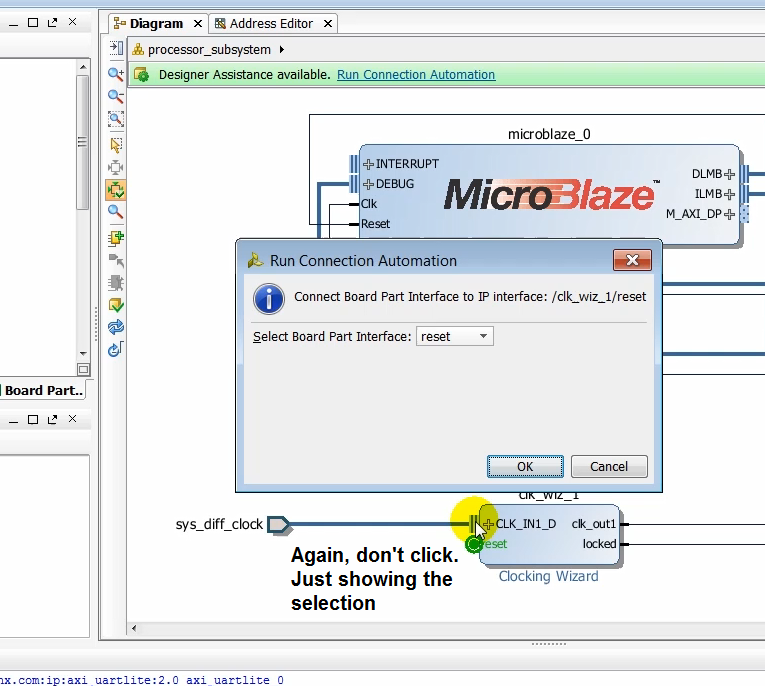
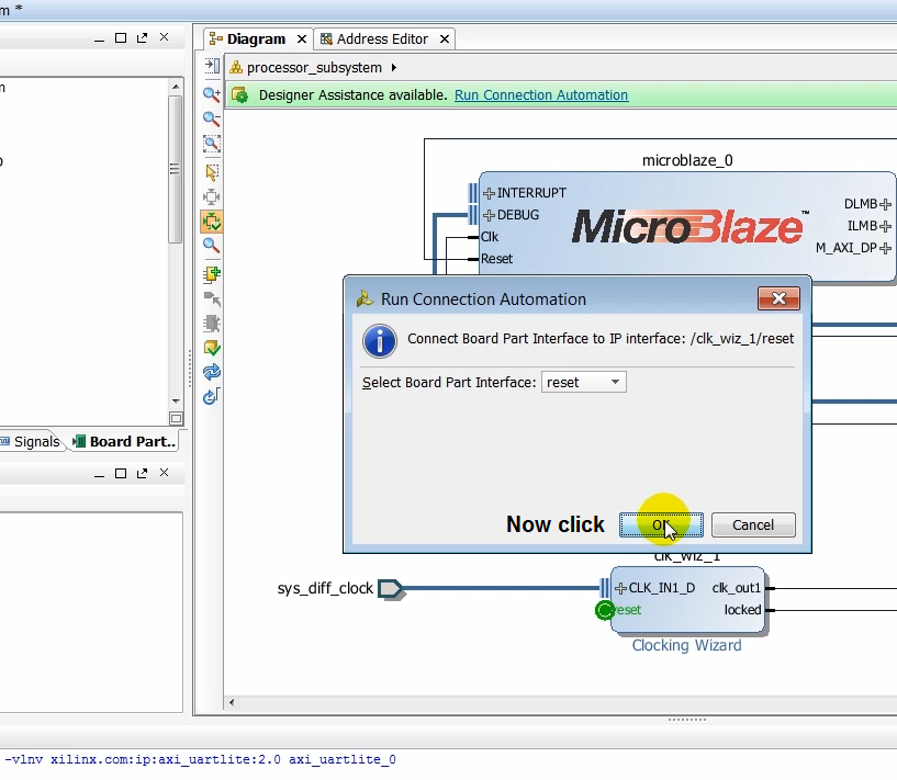
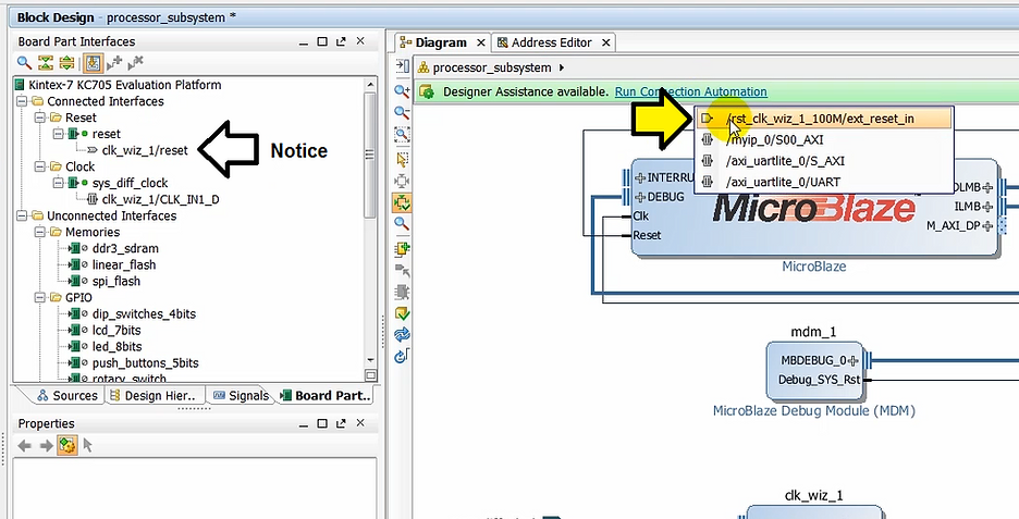
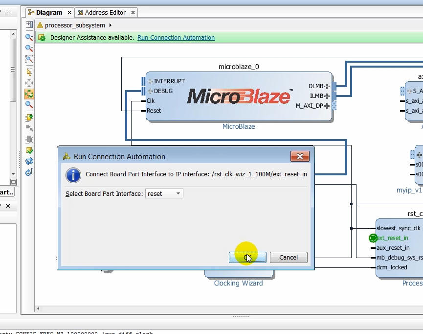
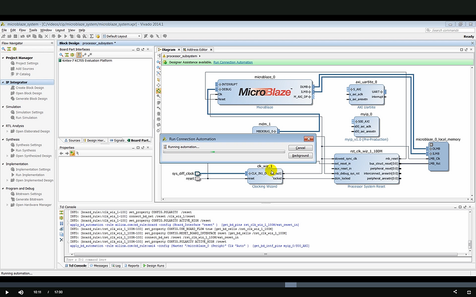
(10:07) We only need to use the clock reset on the UART interfaces in this design. Use all of the items that are connection automation link to complete the connectivity of the design.
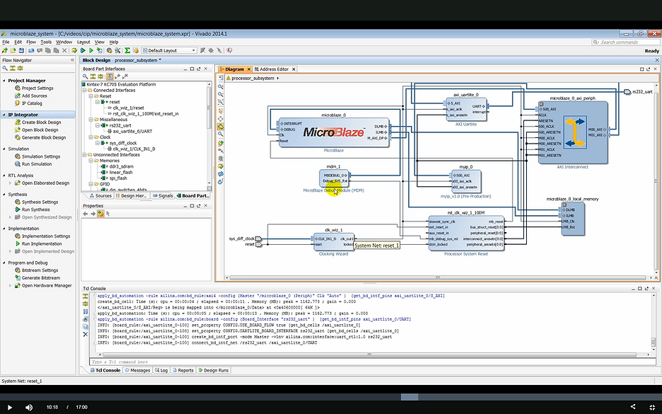
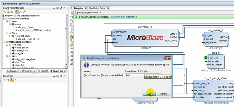
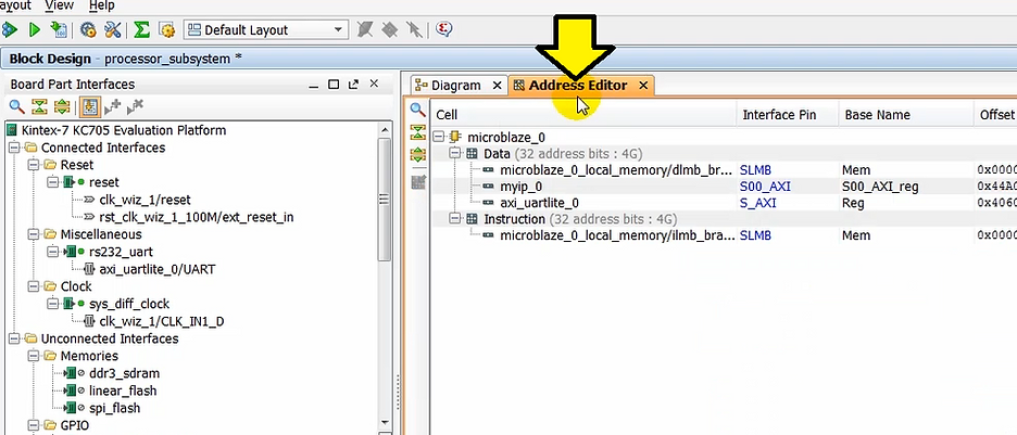
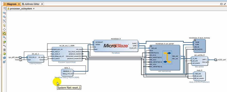
(10:21) With the design now complete let’s make sure that the memory mapping for all the slaves in the design has been done correctly. As the slaves are instantiated in the design IP integrator assigns the memory to each of these automatically. This memory mapping can be changed their desire. In this case, we’ll leave the default memory map.
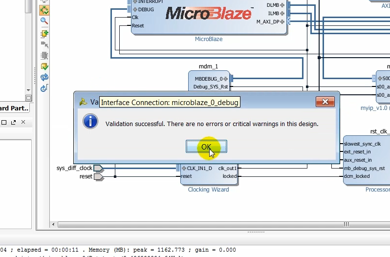
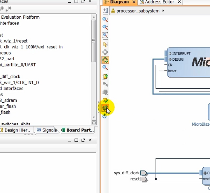
(10:39) At this point, we’re ready to validate the design.
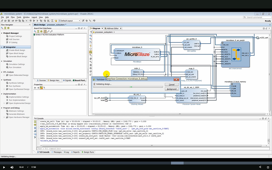
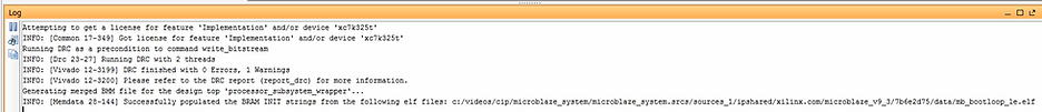
(10:43) Validating runs design rule checks on the design running DRC successful, and there are no design errors in this case.
(10:51) We can tidy up the design and generate an optimum layout of the design by clicking on regenerate layout.
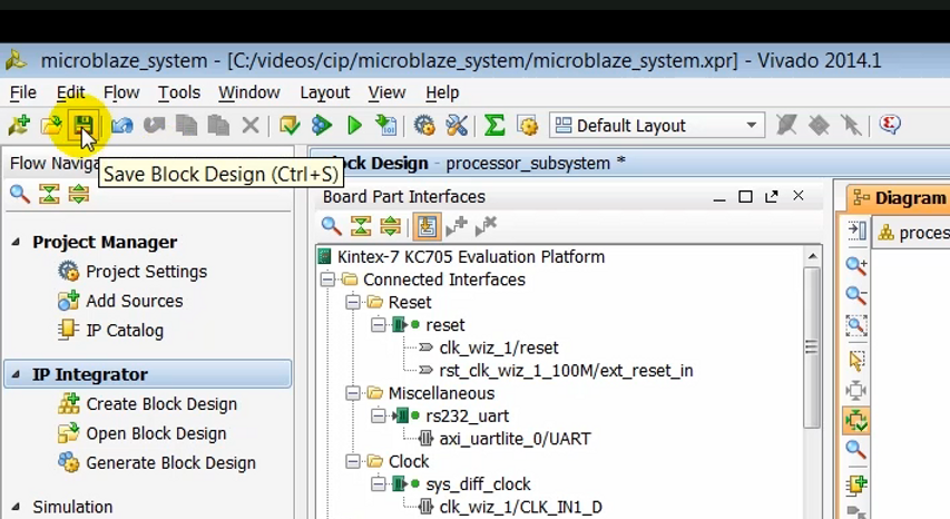
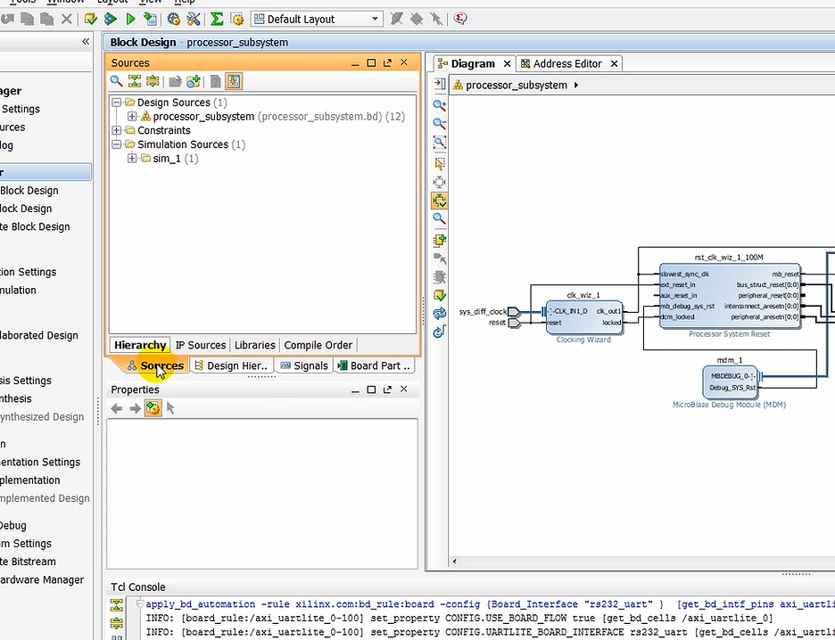
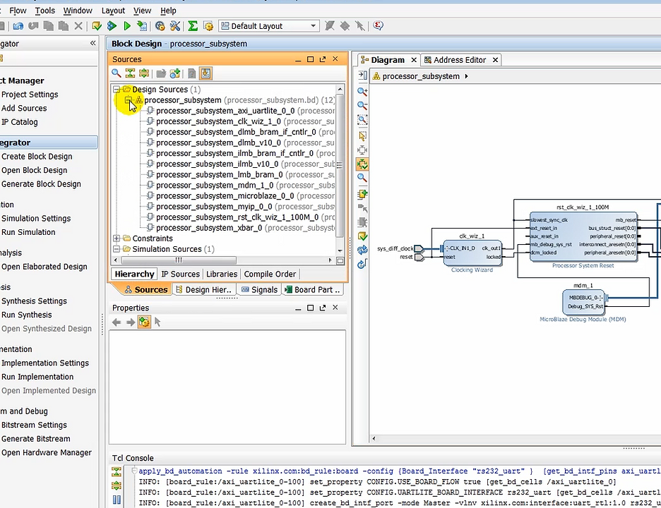
(10:55) At this time, we can save the block design.
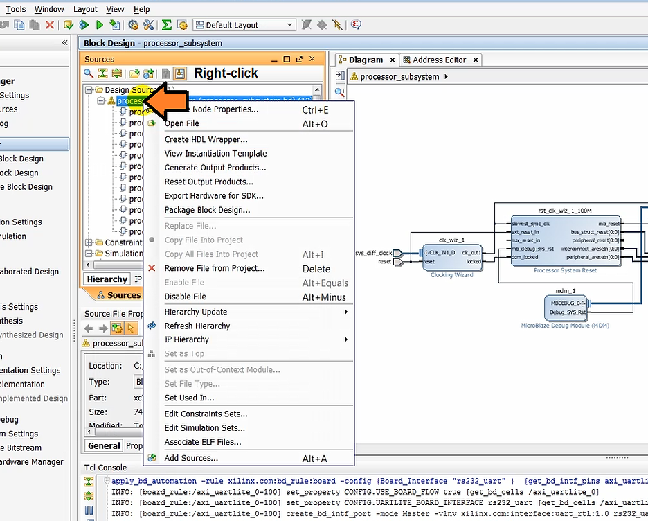
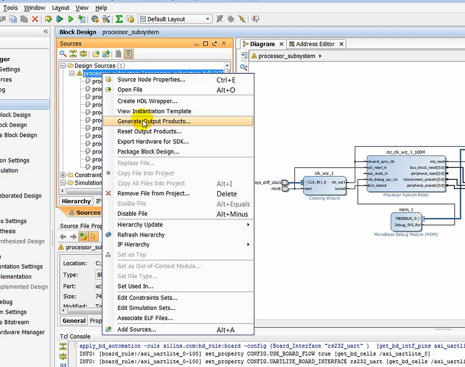
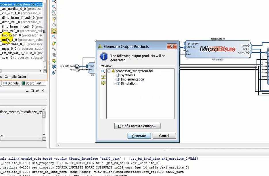
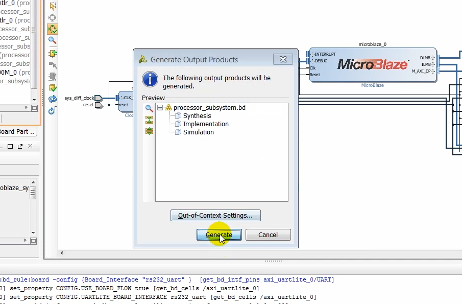
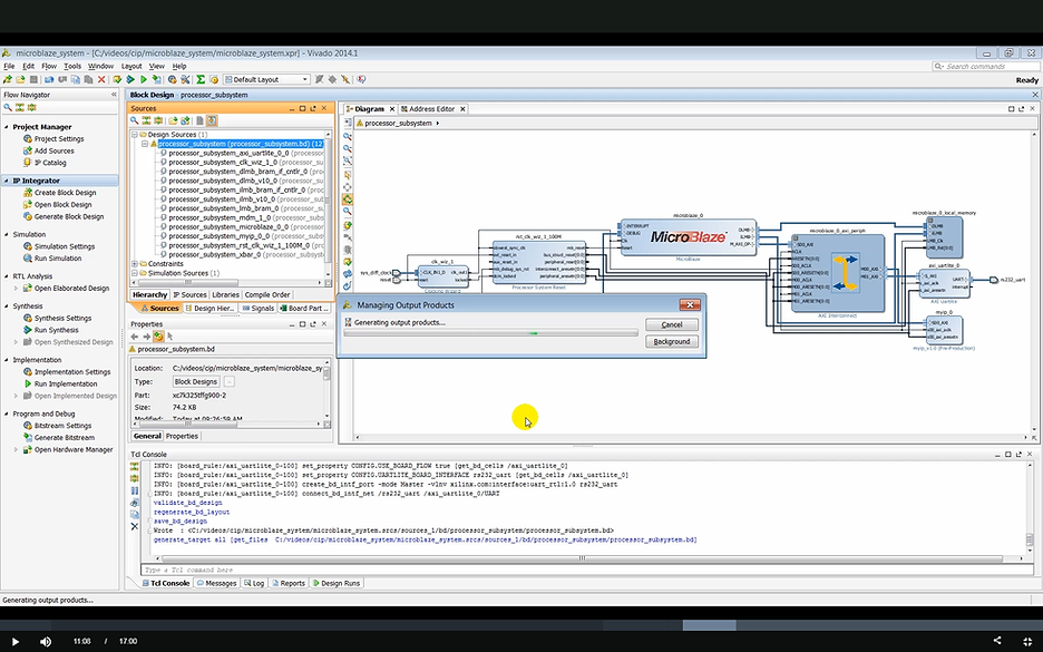
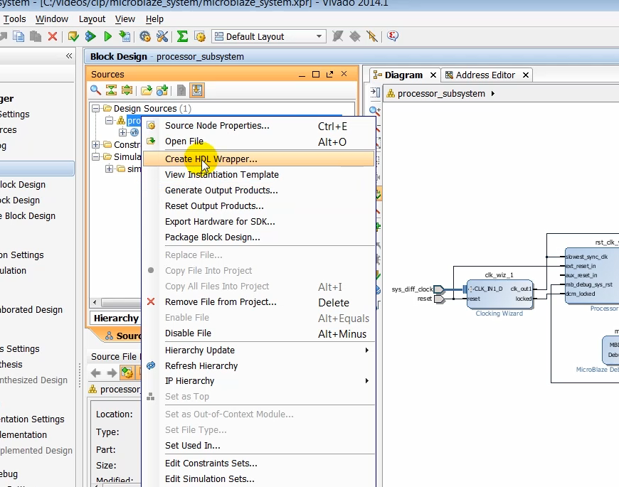
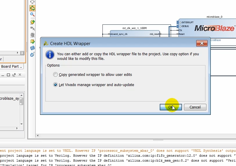
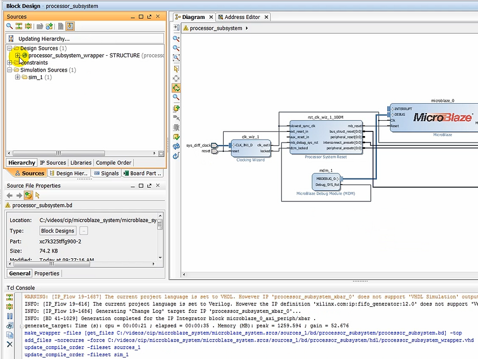
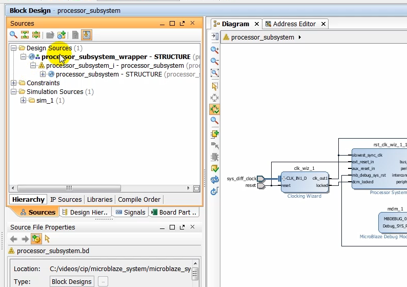
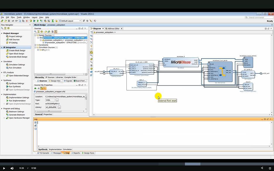
(11:01) With a block design now complete regenerate outward products and create a top level wrapper file that instantiates a block design in it.
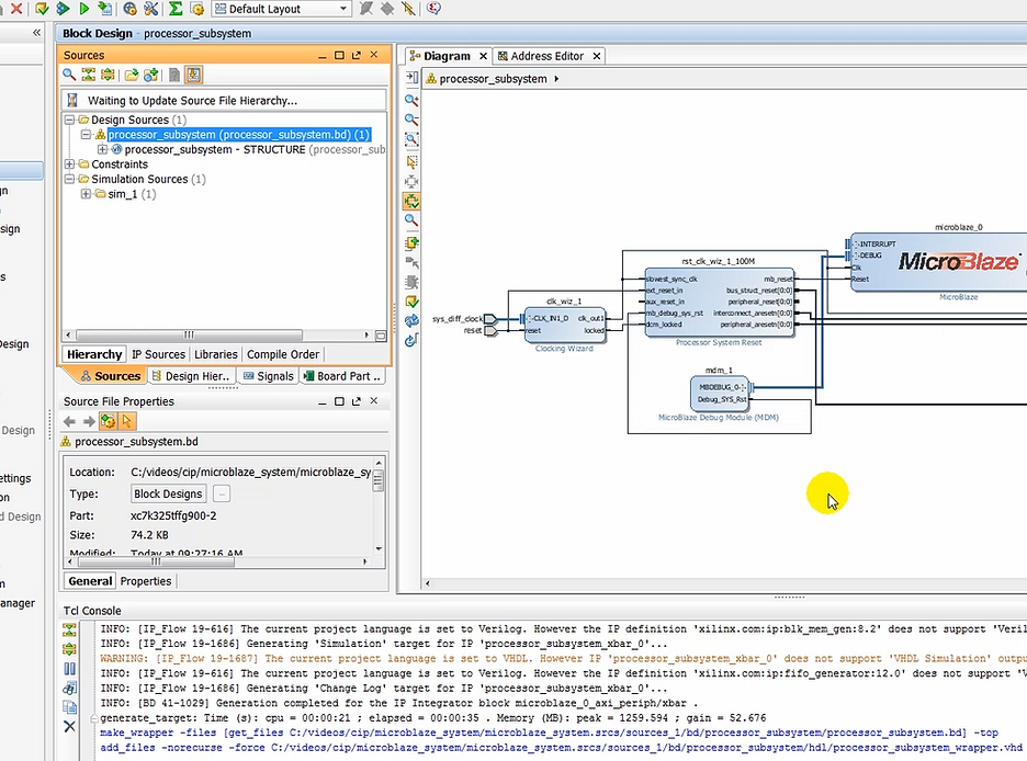
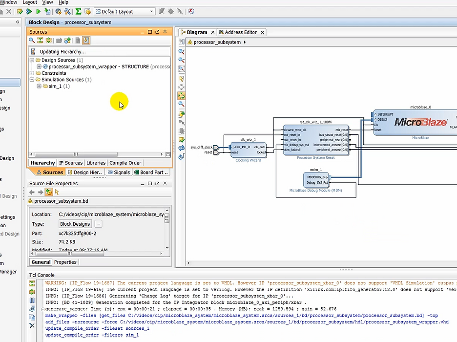
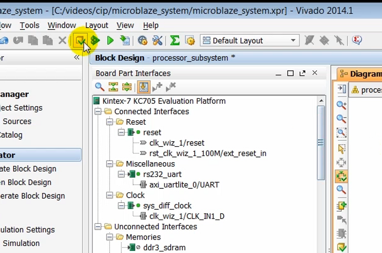
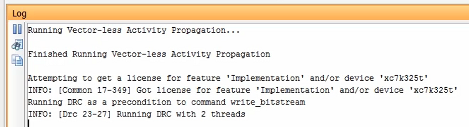
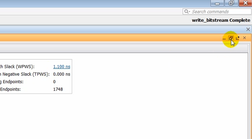
(11:18) Now we need to implement the design, which kind of be done by clicking on generate bitstream street, which will take the design to synthesis, implementation and finally generate midstream.
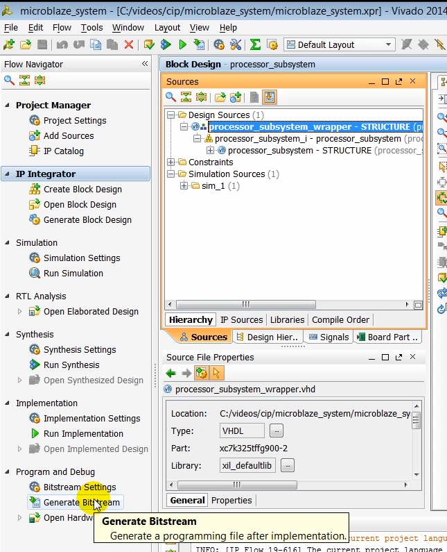
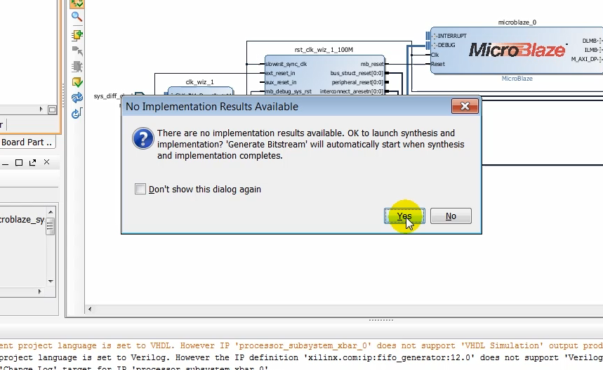
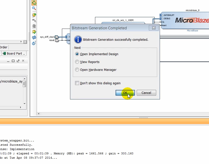
(11:33) Generating bitstream may take several minutes.
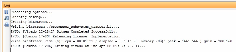
(11:44) After a bitstream has been generated, open the implemented design.
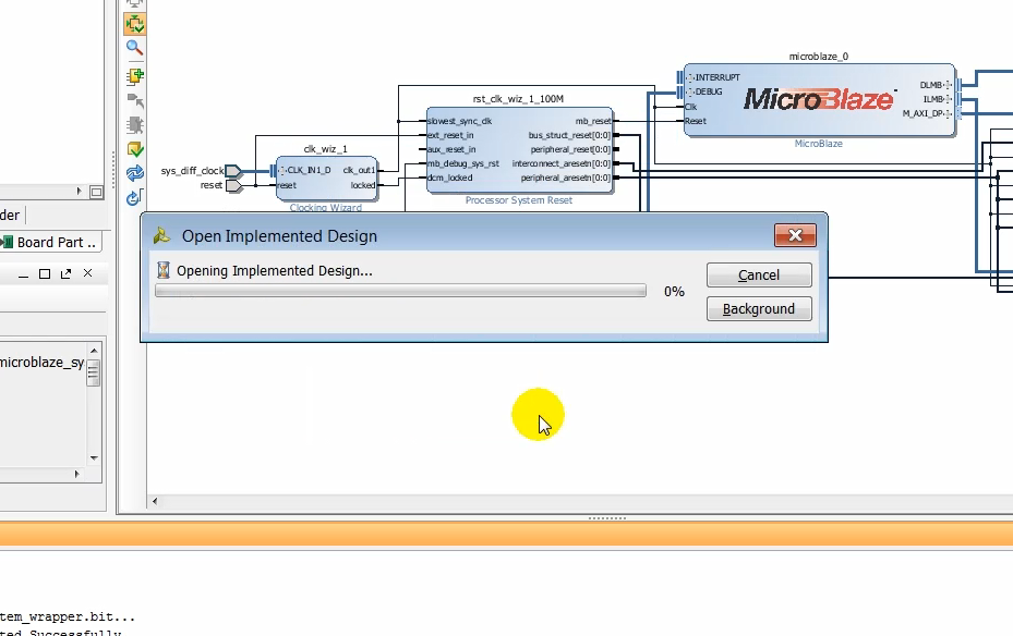
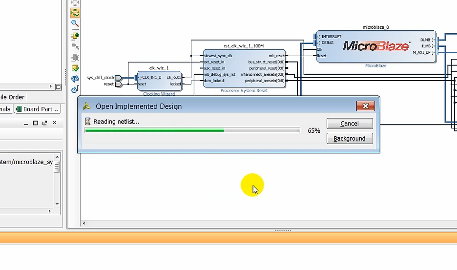
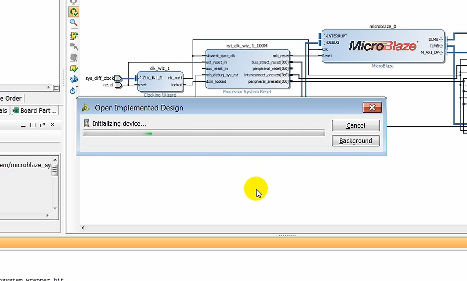
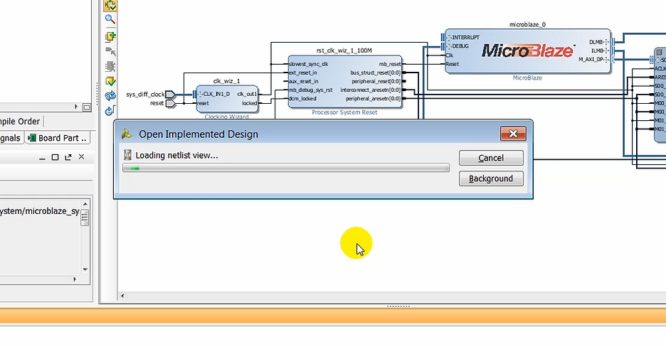
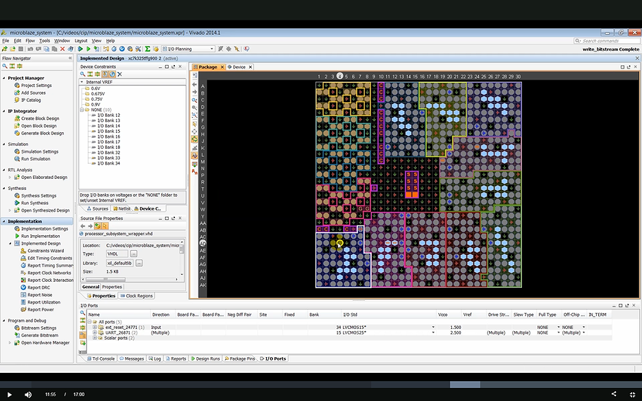
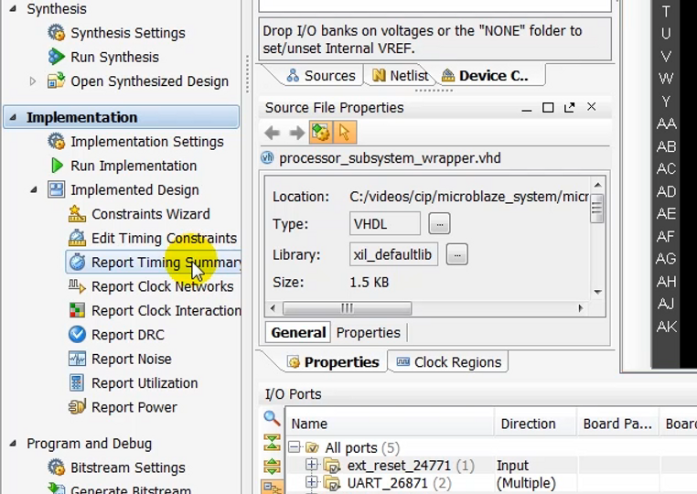
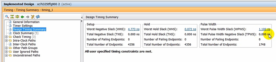
(11:50) Once the implemented design is open, run a timing summary report to make sure that all constraints were met.
Run a Timing Summary to Make Sure Constraints were Met
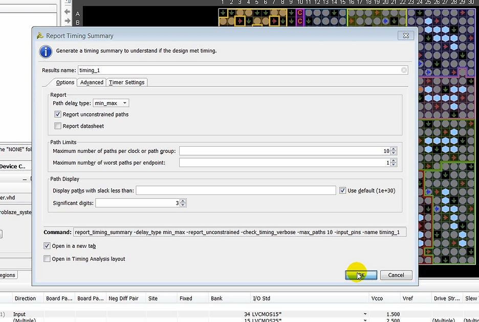
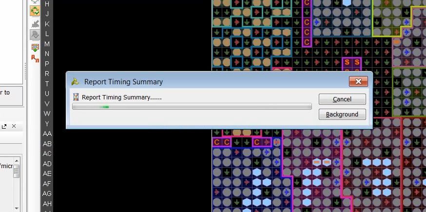
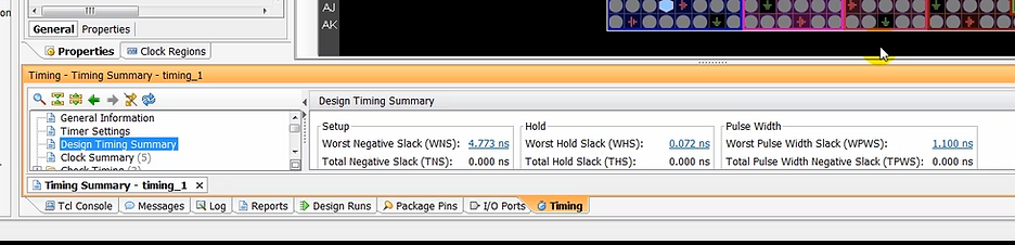
(12:09) Take a moment to look at any set up our hold-time violations.
(12:17) In this case everything is good…
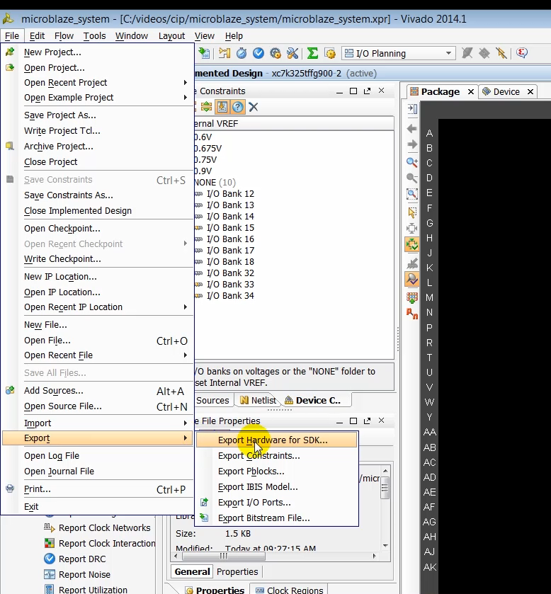
(12:19) …so we need to export the hardware so we can develop our software application. To do this, we’ll export the hardware by selecting export hardware for Sdk.
Export Vivado Hardware to SDK
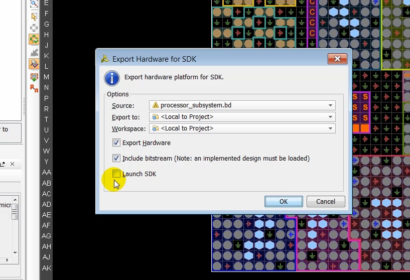
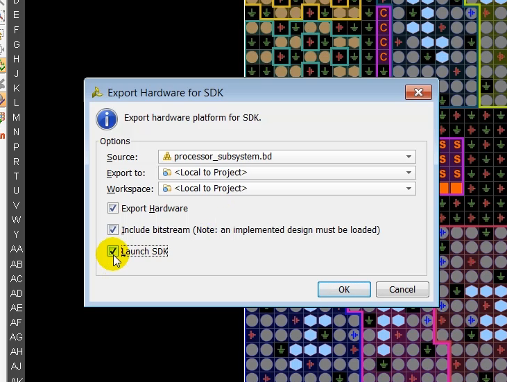
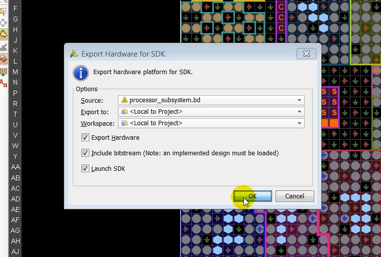
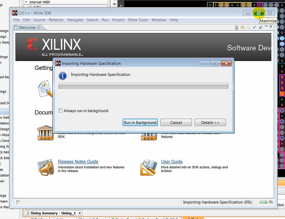
(12:44) While exporting the design, we selected the option to launch SDK, so SDK launches with a new window.
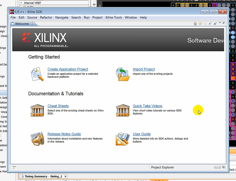
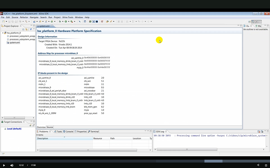
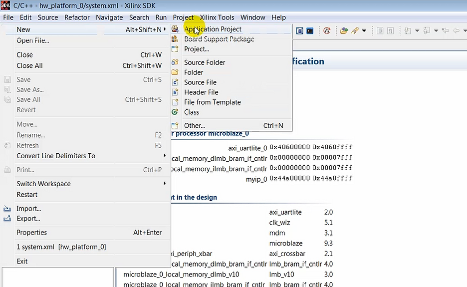
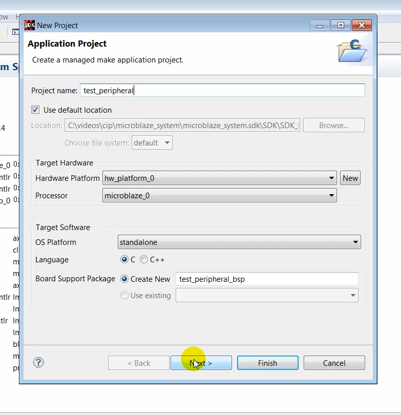
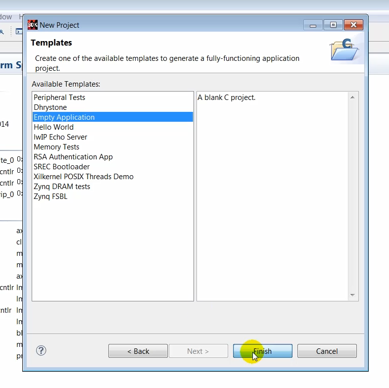
(12:58) In SDK we’ll create an empty application project to which we can add some code to exercise the AXI port peripheral on the KC705 target hardware. Lets create an empty application first by creating a new application project and a specifying a name for the project.
Create a New SDK Project
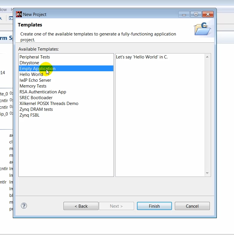
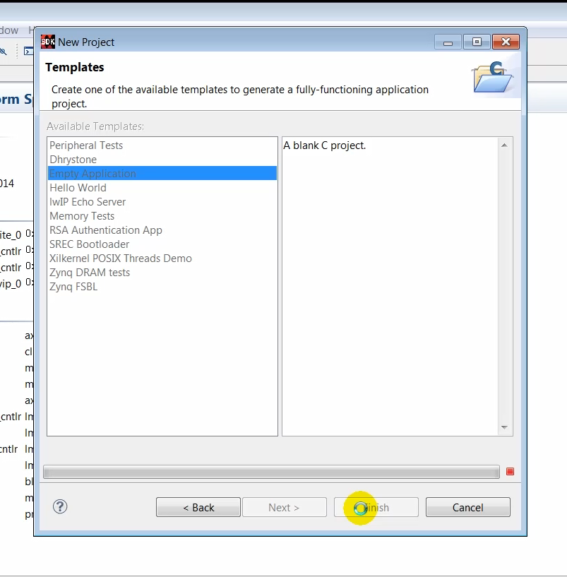
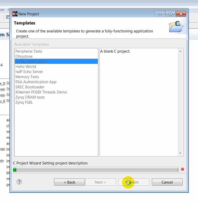
(13:13) In the template space, select to empty application and click Finish
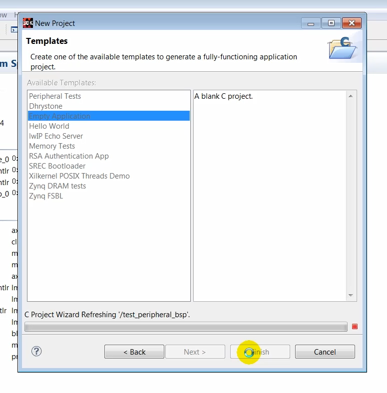
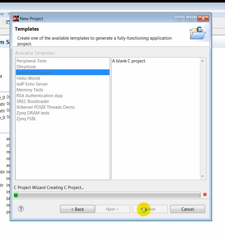
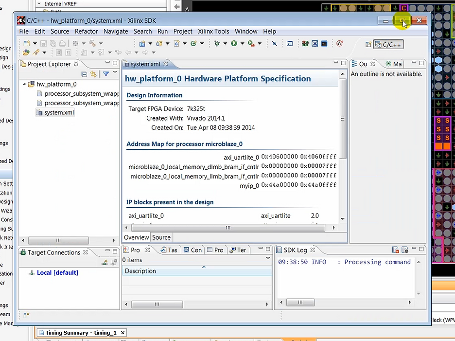
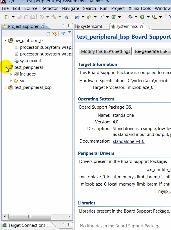
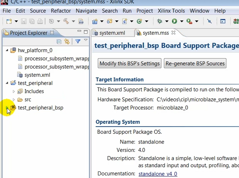
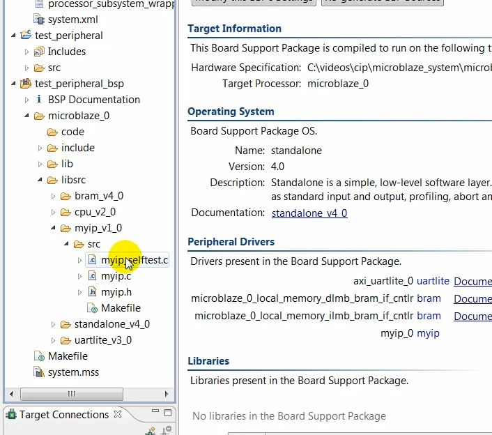
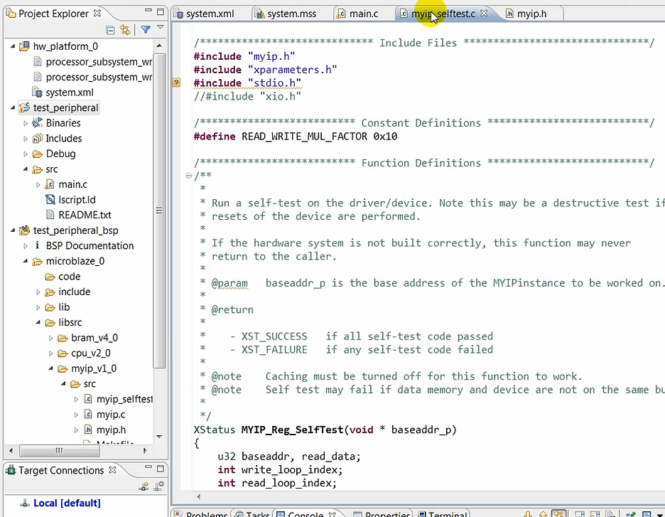
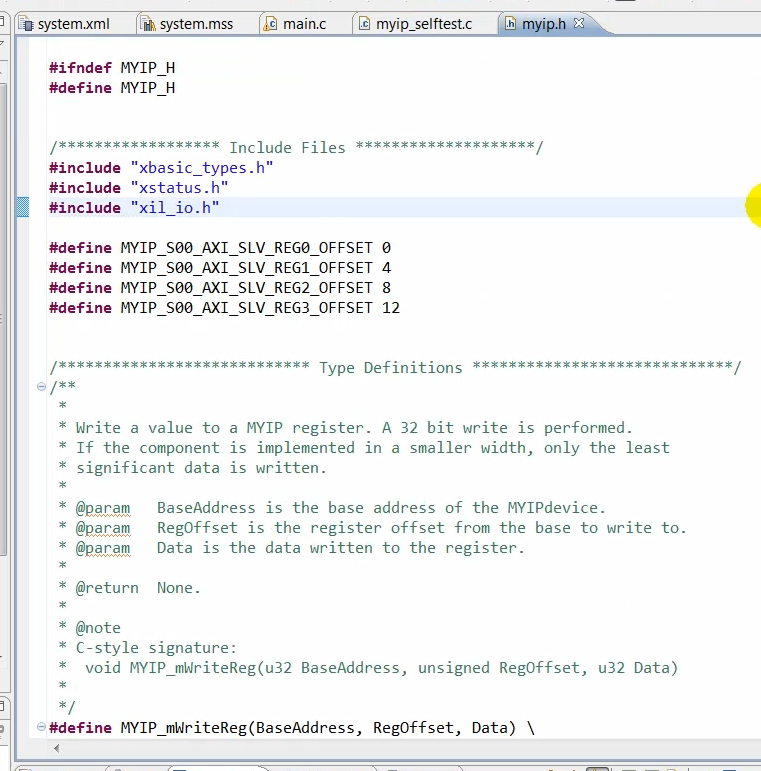
(13:23) While creating the empty application, SDK creates a selftest application for the AXI peripheral, which we created in Vivado earlier.
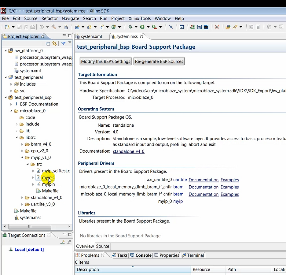
(13:37) This self-test functions need to be called by our custom application code. So essentially what we’ll be doing here is just add a few lines of code in our application to call the function that performs the self-test of the IP. The self-test routine, called myip_selftest, basically writes four bytes of data and reads back those data bytes.
(14:00) So we’ll add a new file. We’ll call this file main.c. In this file is where we will add a few lines of code…
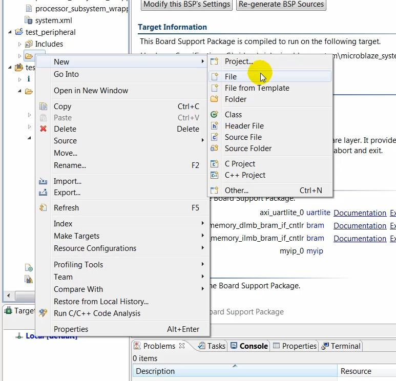
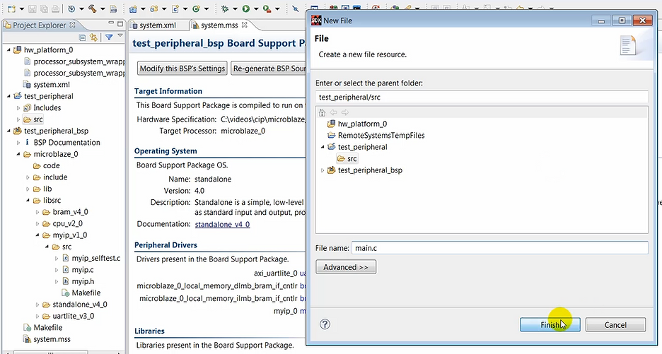
Note: the following file was created by the video creator not by the tool. This means you’ll need to type this info in.
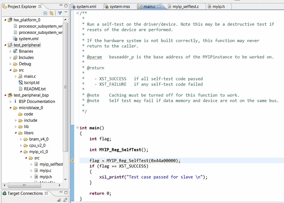
(14:16) …to call the function that was created earlier for exercising our AXI peripheral IP.
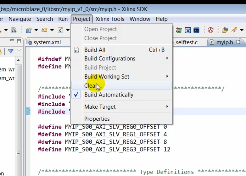
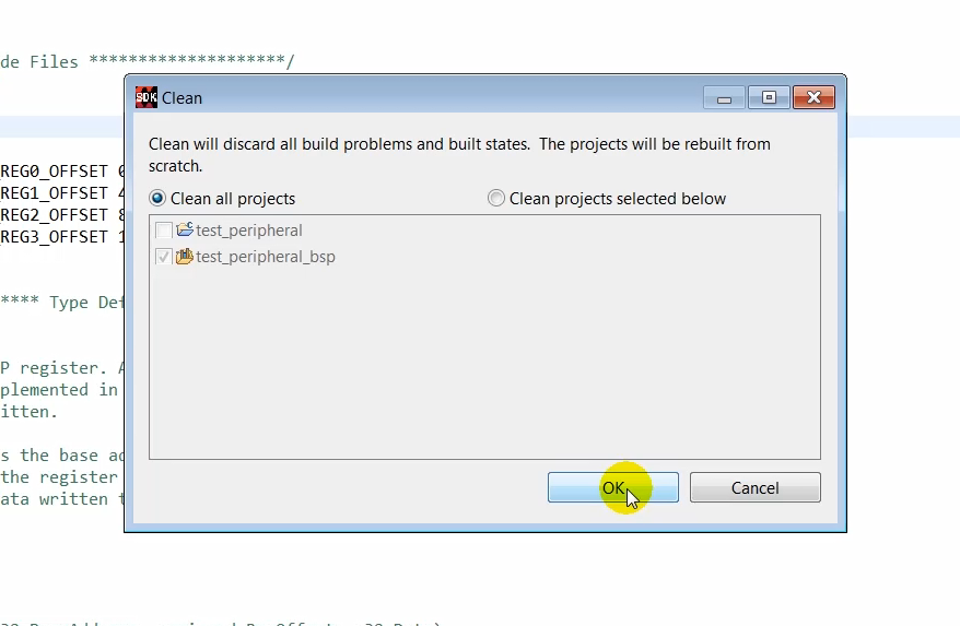
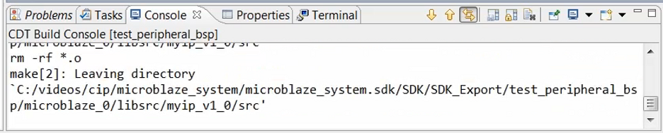
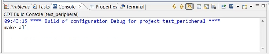
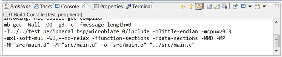
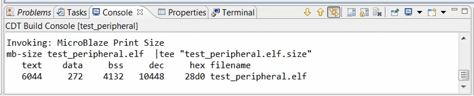
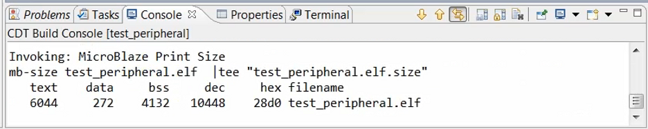
(14:23) Now we are ready to compile this code.
Click:
Output:
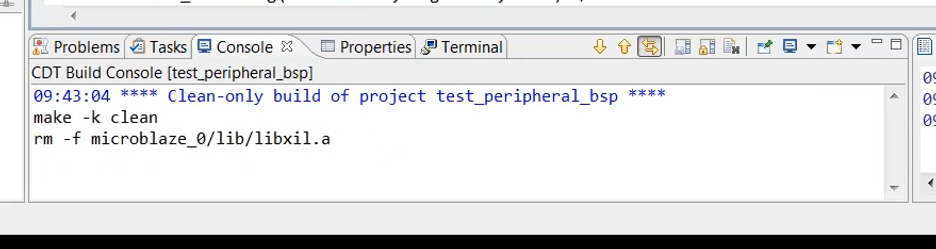
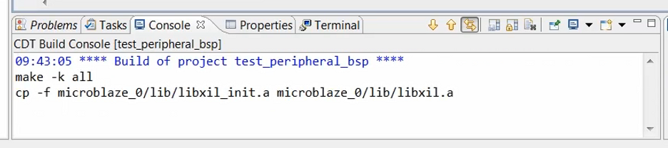
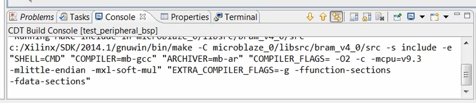
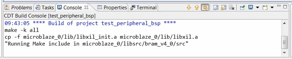
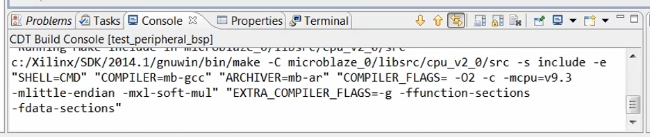
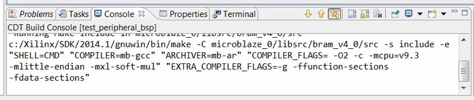
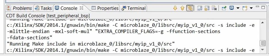
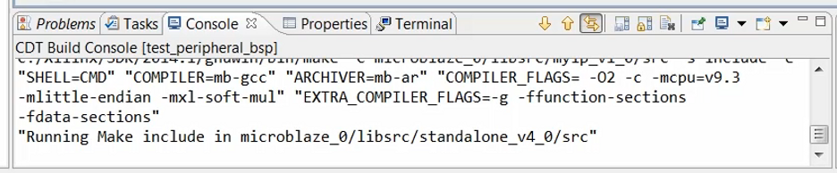
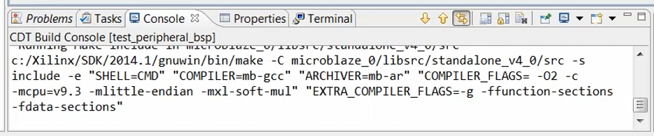
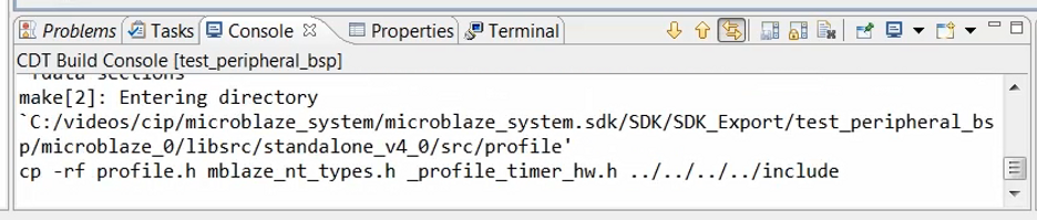
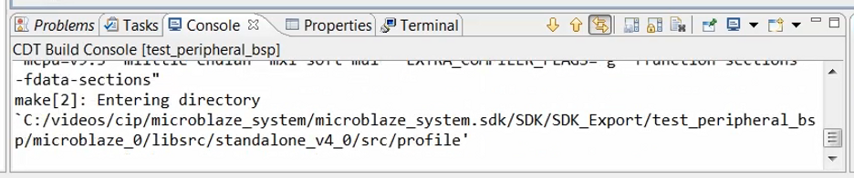
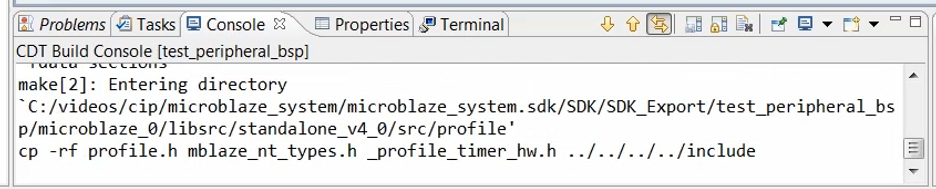
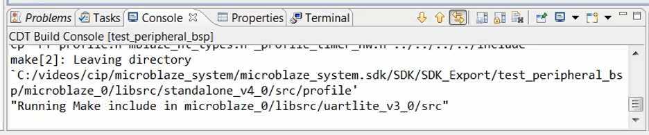
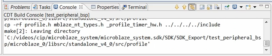
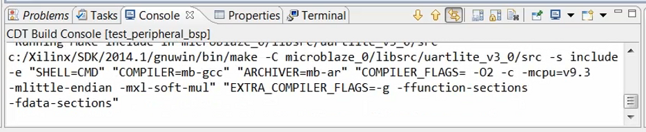
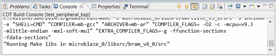
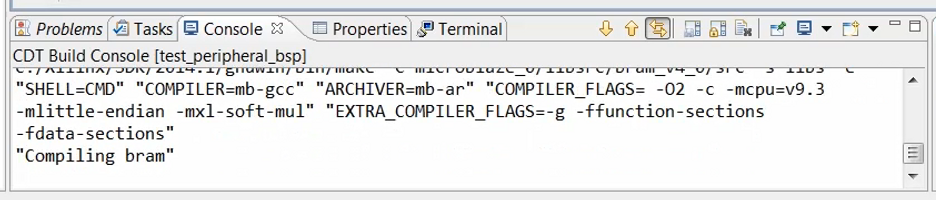
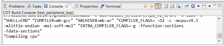
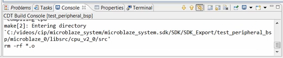
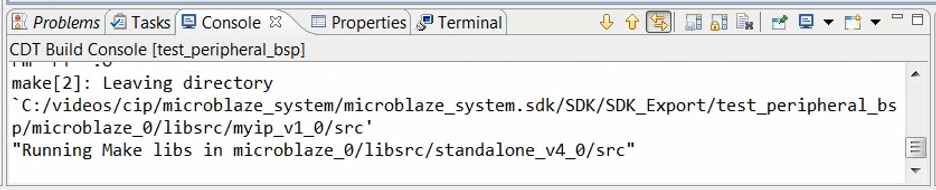
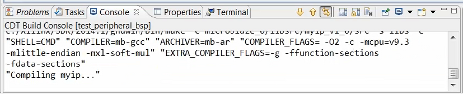
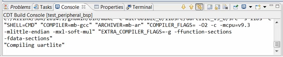
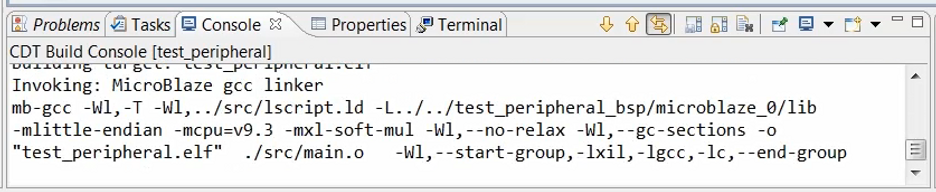
Note: linker running
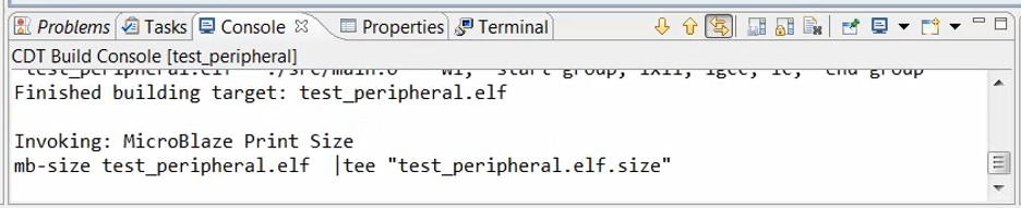
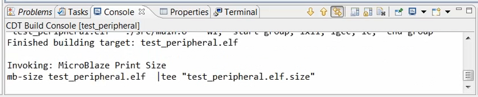
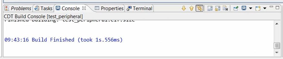
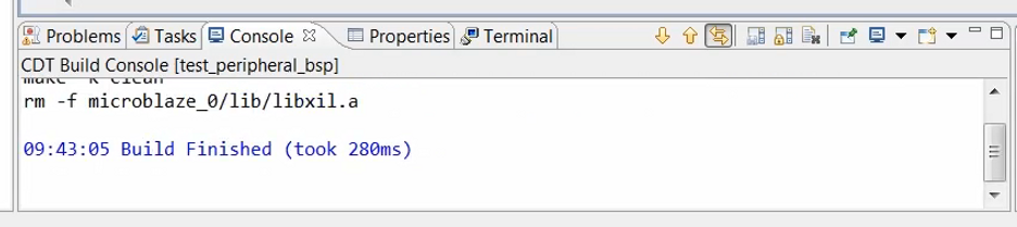
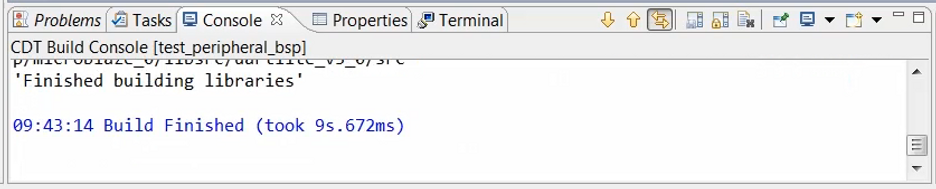
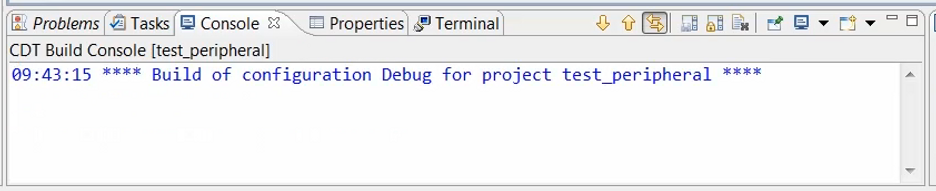
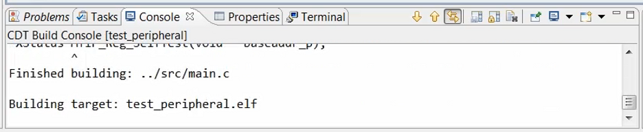
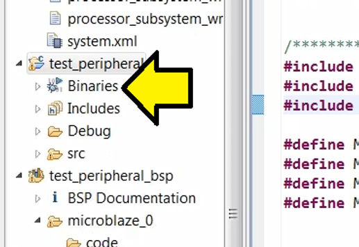
Note: the Binaries node pops up coincident with Build Finished (took 1s.556ms)
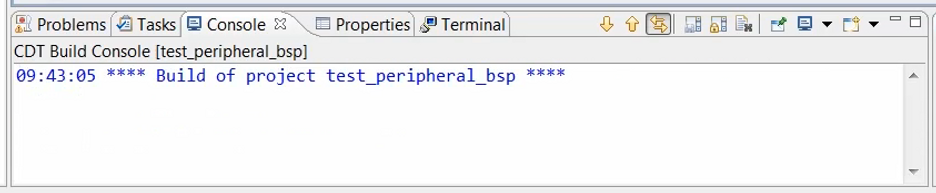
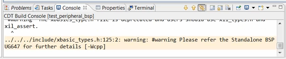
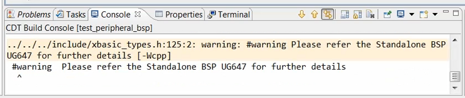
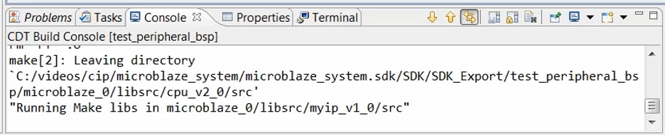
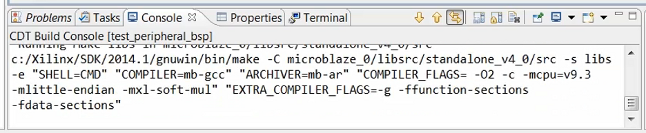
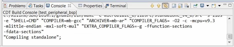
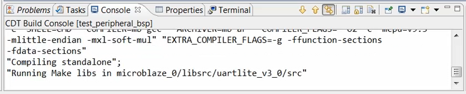
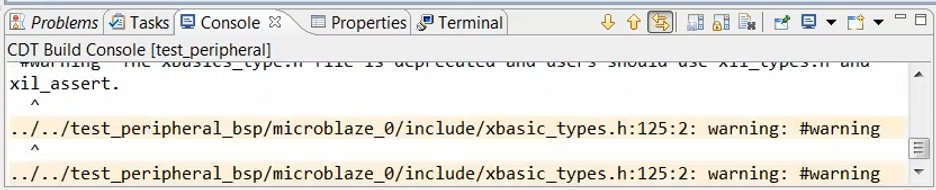
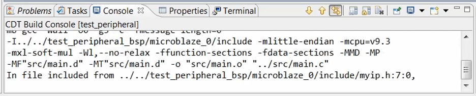
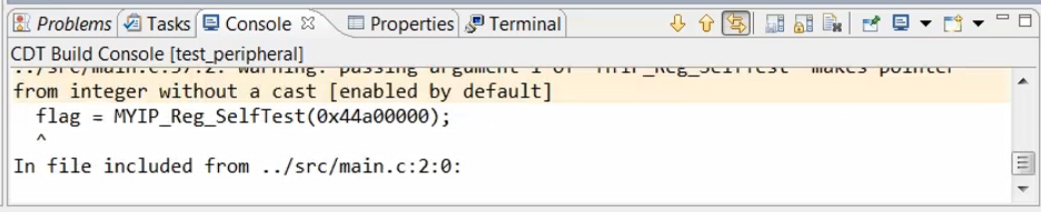
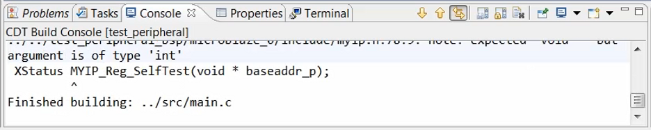
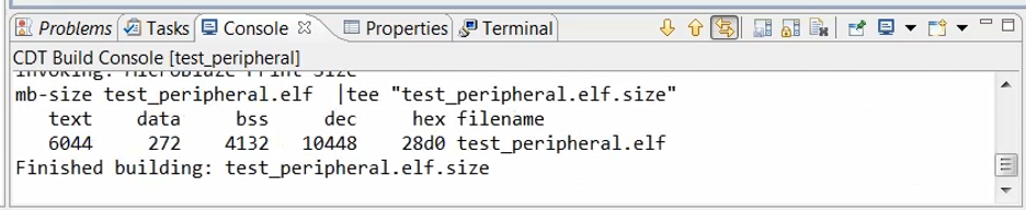
(14:44) Once compilation has done, take a to look at the console for any warnings or errors that may have been flagged during the process.
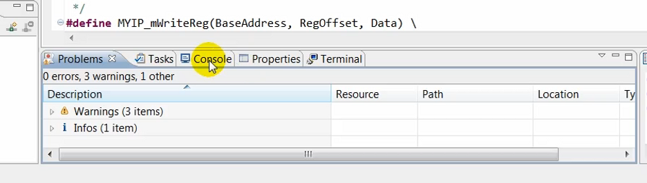
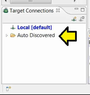
(14:47) In this case, it appears that everything is good, so we’ll connect the monitor to monitor the communication between the hardware and the software.
Click:
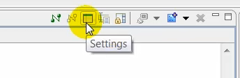
Click:
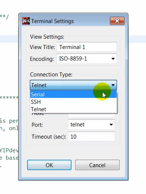
Click:
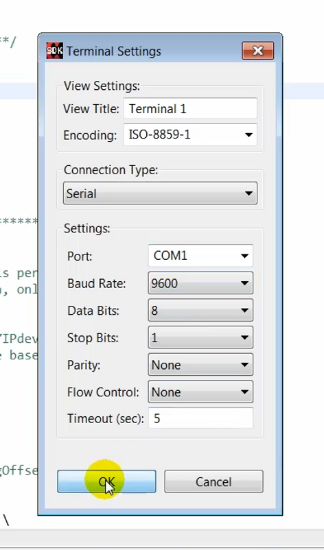
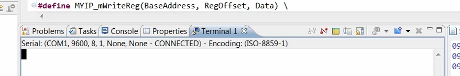
(15:10) With the monitor connected…
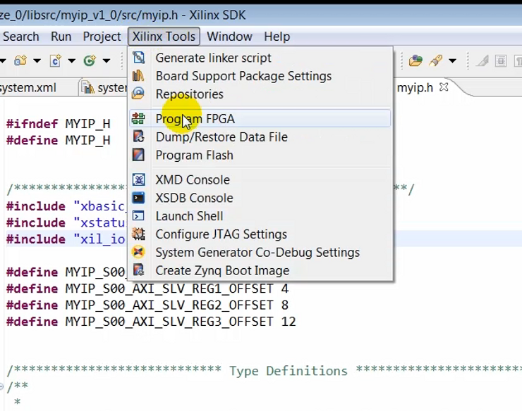
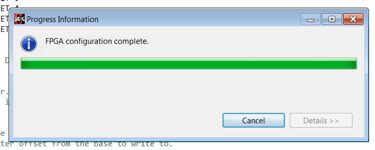
(15:14) …we’re ready to program the FPGA.
Click:
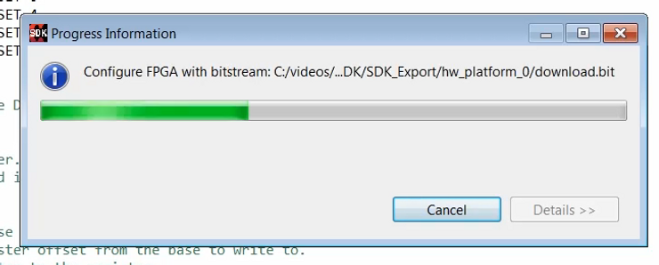
(15:19) Make sure that the bitstream selected is the correct bitstream for the project.
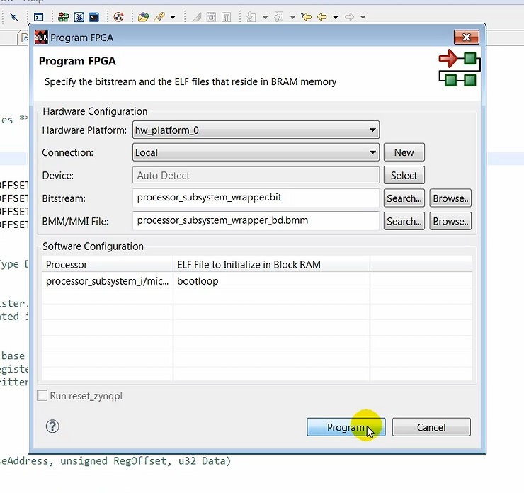
Output:

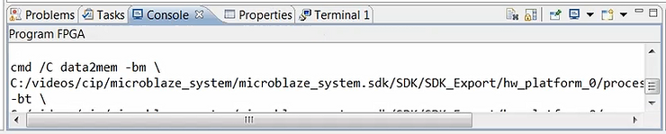
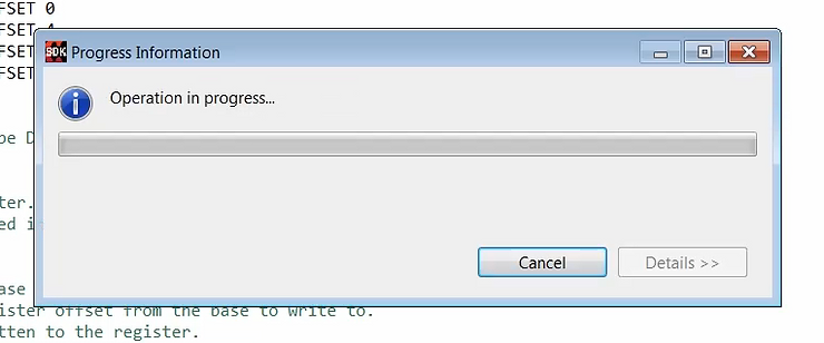
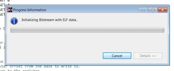
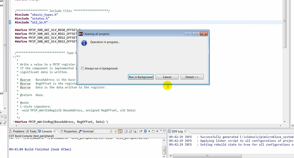
(15:32) Programming the FPGA may take a minute or so.
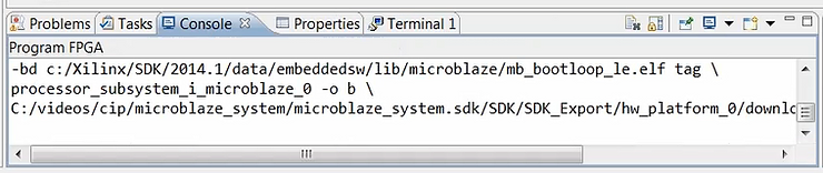
Output:
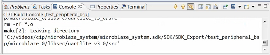
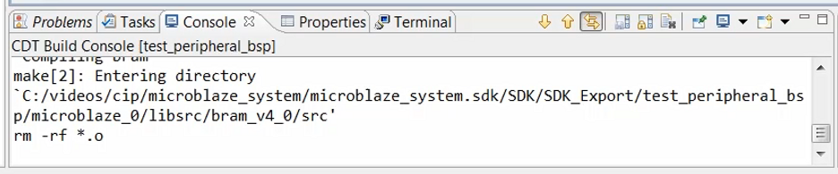
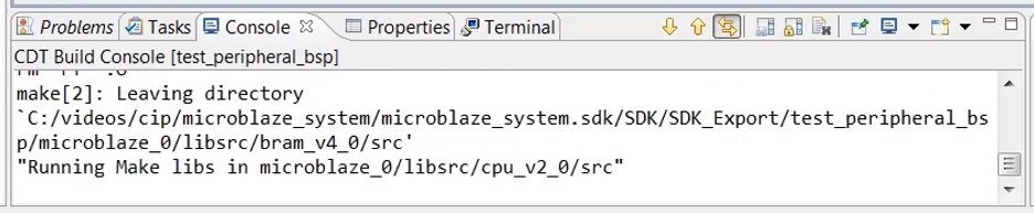
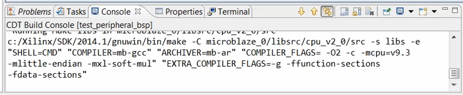
…and:
Output: there is a recompile of the source files whose output matches the output above. The output is not shown again here.
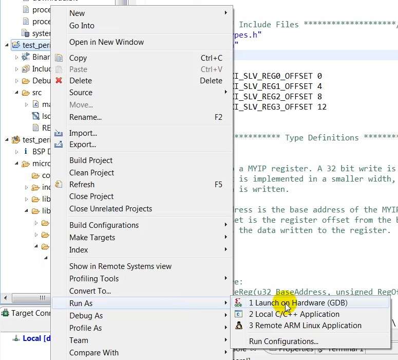
(15:37) Now that the FPGA has been programmed we can launch the ELF file onto the hardware. To do this, we’ll select the application code that we just created and launch it on hardware.
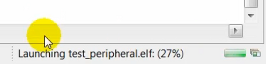
(16:00) Well, the bottom right of the window, you can see that the code is being launched on hardware:
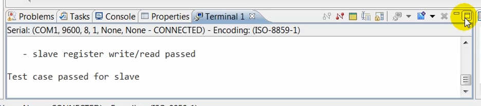
(16:07) …and on the terminal you will see the results of the cell test that was performed.
Click:
Output:
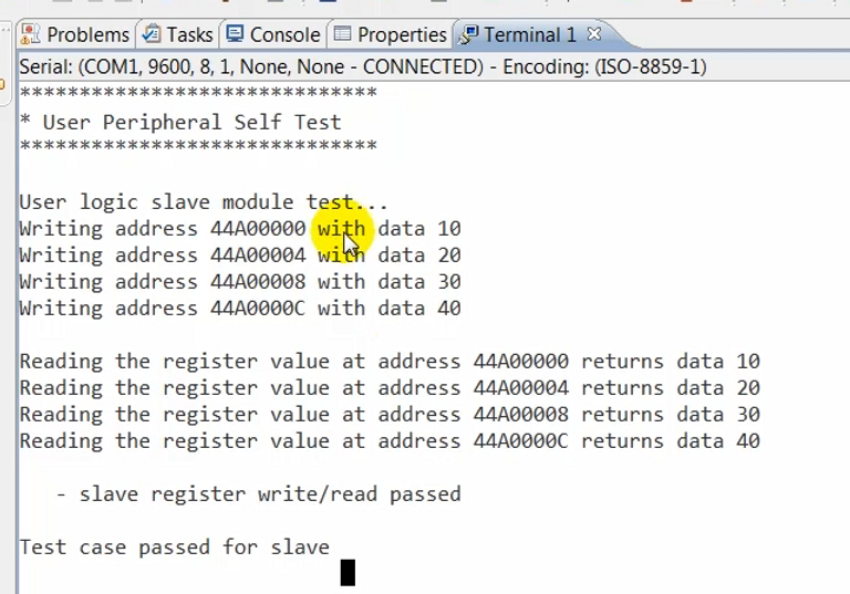
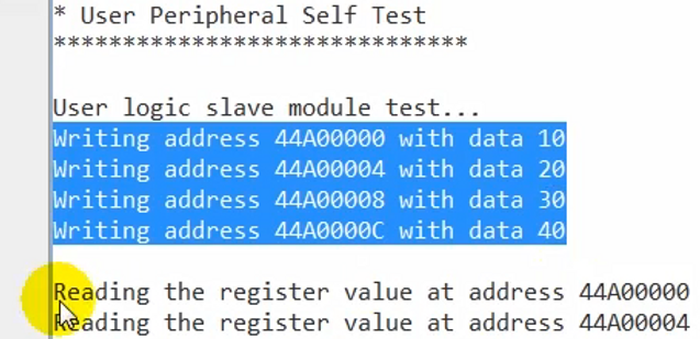
(16:14) The terminal window shows that four write transactions were performed …
(16:17) …followed by four read transactions…
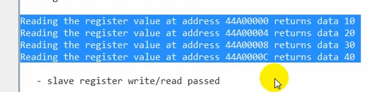
(16:18)…and the data for the write and read matches.
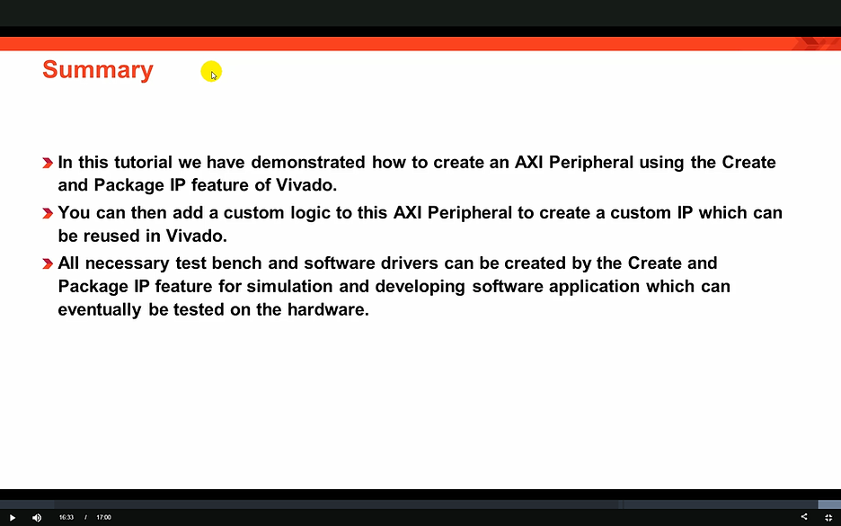
(16:32) So in this QuickTake Video, we have created a new AXI peripheral, simulated it using an AXI bus functional model and then verified ts functionality on a KC705 board in a MicroBlaze based design. We have seen how the create and package IP functionality in Vivado allows you to create a master or a slave AXI peripheral, which can be used to create a custom IP.
(16:53) Thanks for watching the Quick Take video.
Tools Used