
Zynq-7000 + AXI Slave CDMA controller on a ZC702
![]()
This post lists step-by-step instructions for creating an AXI slave Central Data Management Access (CDMA) controller, integrating the slave into a Zynq-7000 system using Vivado, writing a driver that exercises the CDMA, and running everything on a ZC702. More commonly referred to as DMA, DMA’s are useful for passing data between a CPU (in this case, the Processing System (PS)) and external peripherals. DMA allows the PS to be idle while transfers are happening, freeing up the PS to do other things, and access the data when it’s convenient for the PS to do so. Use cases include reading/writing to memory, to a radio controller, HDMI, Serial Busses, etc.
As shown in the high-level diagram below, this design uses general-purpose AXI to interface the ARM A9 processor with the CDMA, and high-performance AXI to interface the CDMA with DDR memory on a ZC702 prototype board. Pseudo-random data is stored and read back in a two transaction CDMA transfer. The returned data is compared with the sent data to verify the CDMA transaction completed successfully.

Credit: Xilinx
Versions Used
Xilinx Vivado 2018.2 & SDK 2018.2
ZC702 Rev 1.1
Windows 10 Professional v1909
Before you Start
Review the ZC702 JTAG and serial port set up instructions @ [link]. These instructions are also reviewed below.
Contents
Part 1: Create the Vivado Project
Part 2: Create the Zynq-7000 in IP Integrator
Part 3: Create the CDMA AXI Slave and Concat IP blocks
Part 4: Connect the Interrupt Lines
Part 5: Configure the PS High Performance AXI buses
Part 6: Configure the CDMA
Part 7: Automate remaining connections
Part 8: Address configuration
Part 9: Create a Top-Level HDL Wrapper
Part 10: Synthesize and Generate the Bitstream
Part 11: Export the Design and Open the SDK
Part 12: Install the USB-to-UART Driver and Get the COM Assignment
Part 13: Configure the Board to Boot from JTAG, Connect it to the PC and Power it On
Part 14: Create the Test App and BSP
Part 15: Test Debug Run + Further Config
Part 16: Test the CDMA Module
Part 1: Create the Vivado Project
Step 1:
A: Press Start
B: Expand Xilinx Design Tools
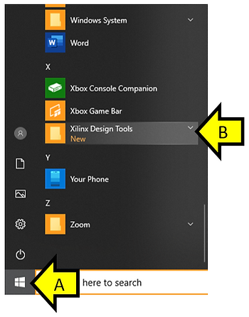
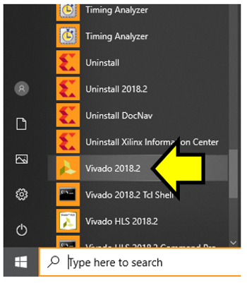
Step 2: Select Vivado 2018.2
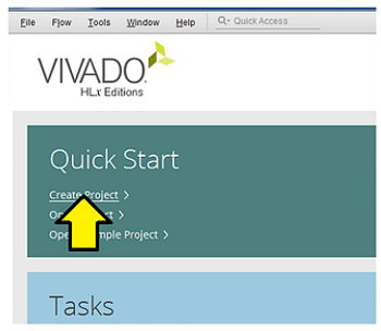
Step 3: Select Create Project
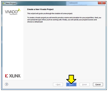
Step 4: Click Next
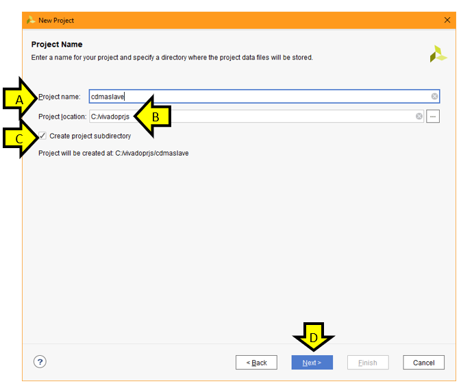
Step 5:
A: Set Project name to cdmaslave
B: Set Project location to C:/vivadoprjs (create C:/vivadoprjs if it doesn’t exist)
C: Click the Create project subdirectory checkbox
D: Click Next
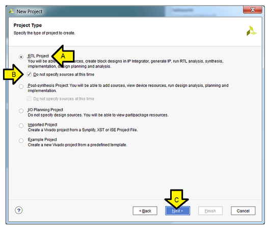
Step 6:
A. Select RTL Project
B. Check the Do not specify sources at this time check box
C. Click Next
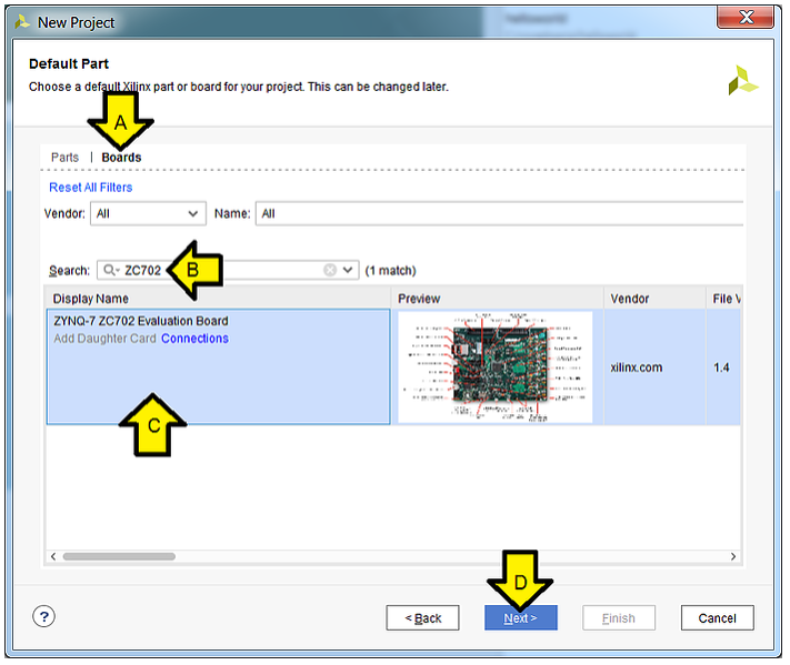
Step 7:
A. Click Boards
B. Type ZC702
C. Click on the ZYNQ-7 ZC702 Evaluation Board box
D. Click Next
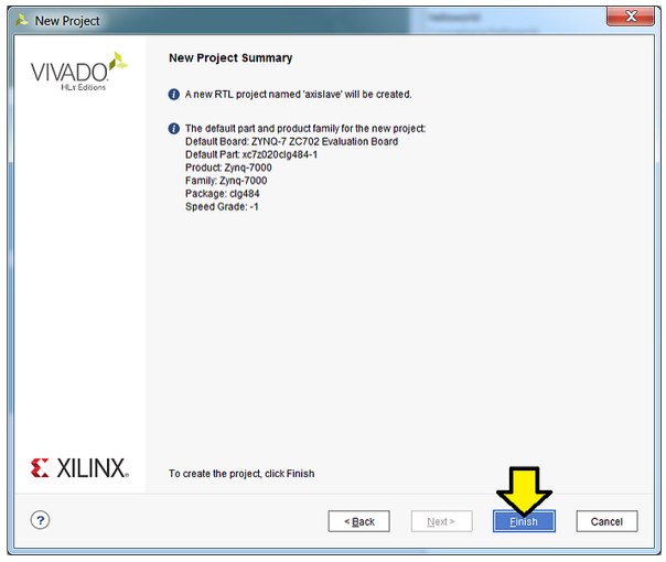
Step 8: Click Finish
Part 2: Create the Zynq-7000 in IP Integrator
Step 1: Click Create Block Design
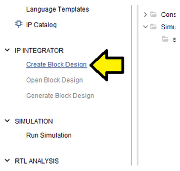
Step 2: Use defaults, click OK
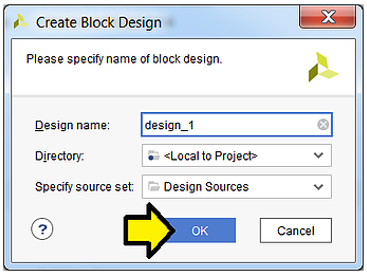
Step 3: Click +
![]()
Step 4:
A. Type Zynq
B. Double-click on ZYNQ7 Processing System
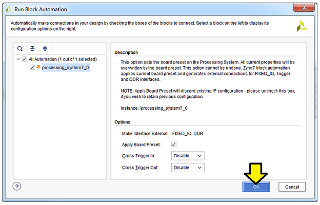
Step 5: Click Run Block Automation
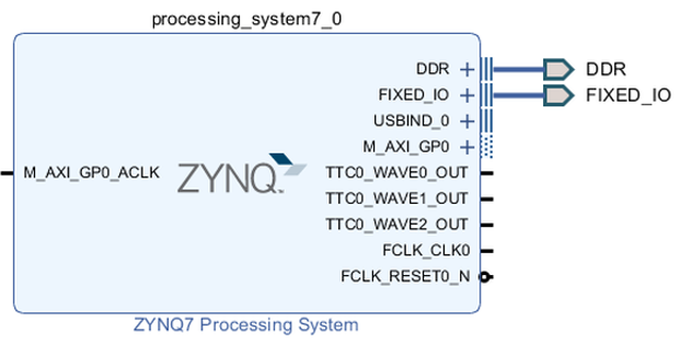
Step 6: Use defaults, click OK
You should see:
Part 3: Create the CDMA AXI Slave, Concat, and Timer IP blocks
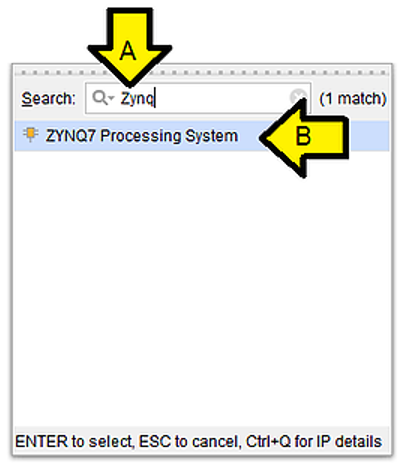
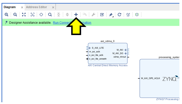
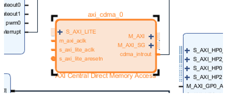
Step 1: Click + again
![]()
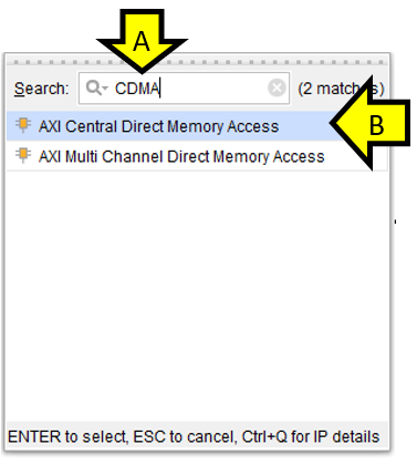
Step 2:
A. Type CDMA
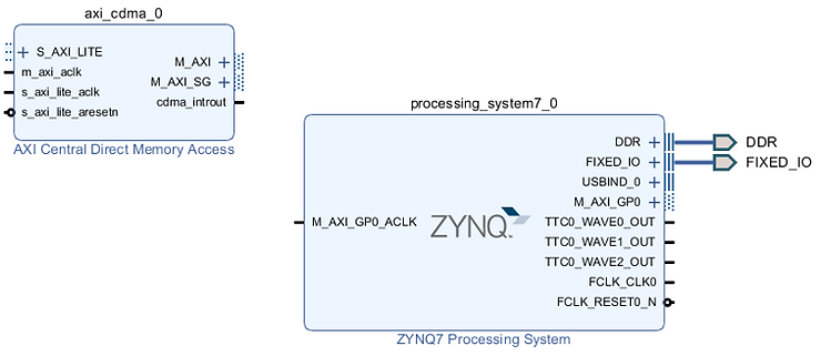
B. Double-click on AXI Central Direct Memory Access
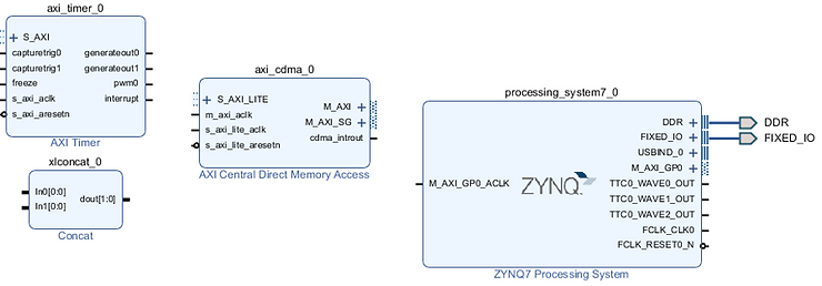
You should now see:
Step 3: Click + a third time
Step 4:
A. Type concat
B. Double-click on Concat
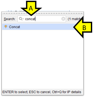
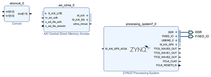
You should now see:
Step 5: Click + one final time
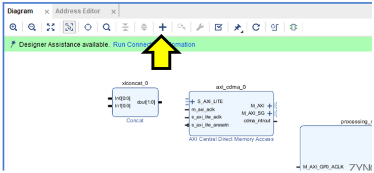
Step 6:
A. Type timer
B. Double-click on AXI Timer
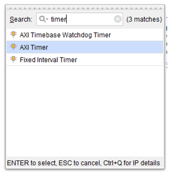
You should now see:
Part 4: Connect the Interrupt Lines
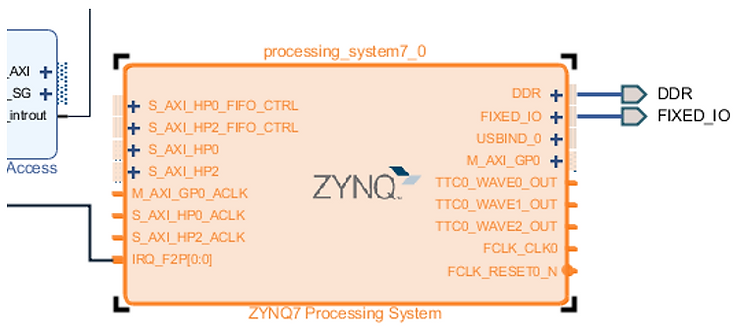
Step 1: Double click the ZYNQ block
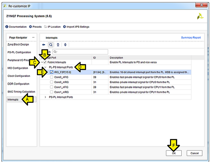
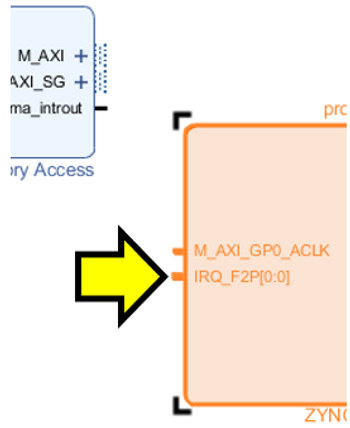
Step 2: Enable IRQ_F2P[15:0]
A. Click Interrupts
B. Check the Fabric Interrupts checkbox
C. Expand the Fabric Interrupts drop-down
D. Expand the PL-PS Interrupt Ports
E. Check the IRQ_F2P[15:0] checkbox
F. Click OK
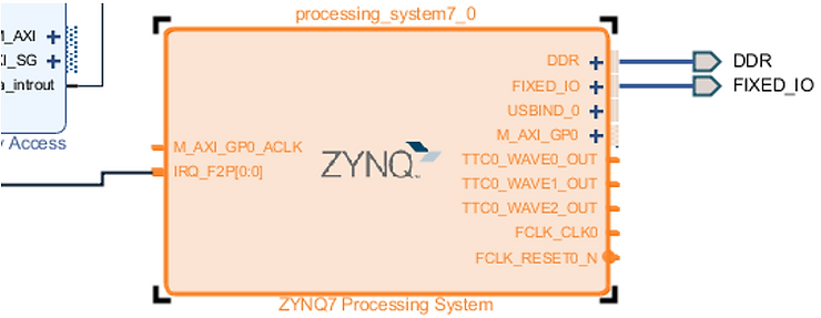
You should then see the IRQ_F2P[0:0] port on Zynq:
Step 3: Connect IRQ_F2P[0:0] to xlconcat_0 interrupt output
A: Click and hold mouse button on IRQ_F2P[0:0]
B: Drag and release mouse button on xlconcat_0 dout[1:0]
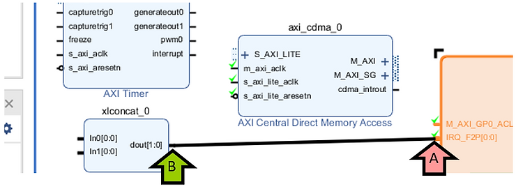
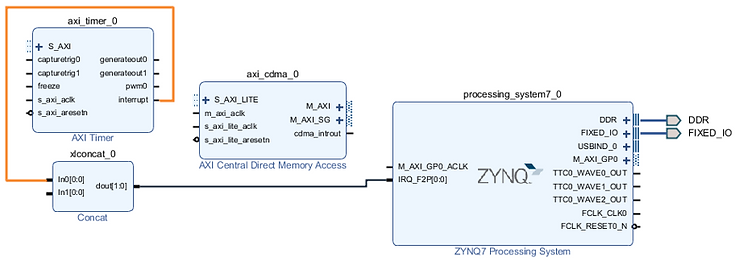
You should see:
Step 4: Connect axi timer interrupt to concatenate block
A: Click and hold mouse button on axi_timer_0 interrupt
B: Drag and release mouse button on xlconcat_0 In0[0:0]
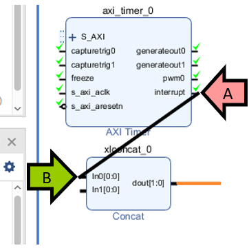
You should see:
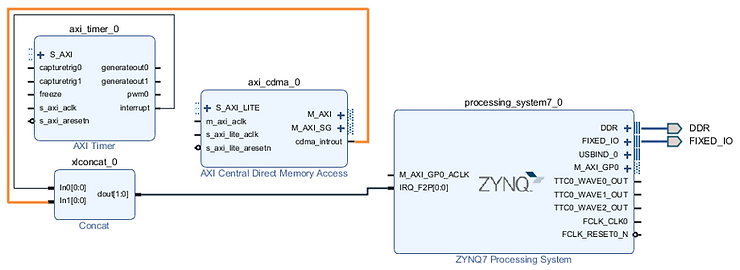
Step 5: Connect CDMA interrupt to concatenate block
A: Click and hold mouse button on axi_cdma_0 cdma_introut
B: Drag and release mouse button on xlconcat_0 In1[0:0]

You should see:
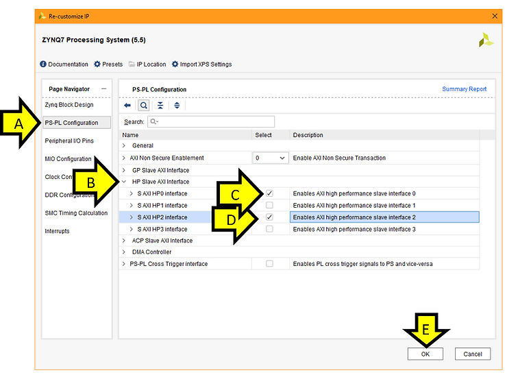
Part 5: Configure the PS High Performance AXI buses
Step 1: Double click the ZYNQ block
Step 2: Enable the High Performance AXI interfaces
A. Click PS-PL Configuration
B. Expand the HP Slave AXI Interface drop-down
C. Check the S AXI HP0 Interface checkbox
D. Check the S AXI HP2 Interface checkbox
E. Click OK
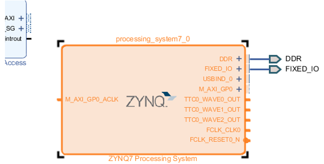
The PS7 should now look like this:
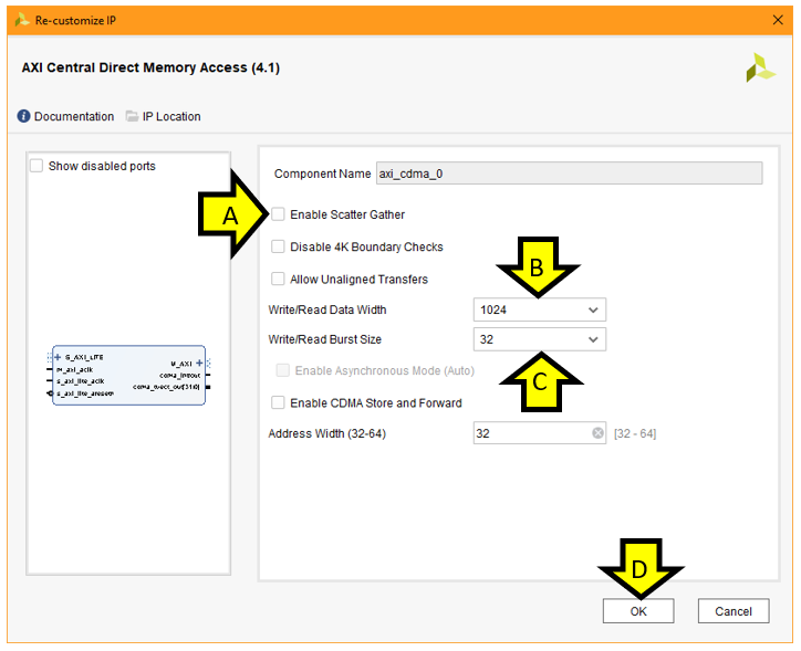
Part 6: Configure the CDMA
Step 1: Double click the CDMA
Step 2: Configure the CDMA
A: Uncheck Enable Scatter Gather
B: Set Write/Read Data Width to 1024
C: Set Write/Read Burst Size to 32
D: Click OK.
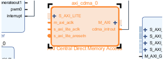
The CDMA IP block should now look like this:
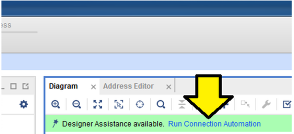
Part 7: Automate remaining connections
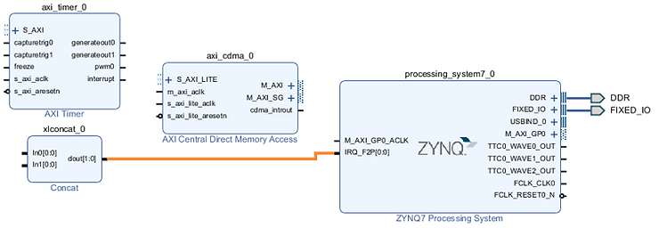
Step 1: Click Run Connection Automation
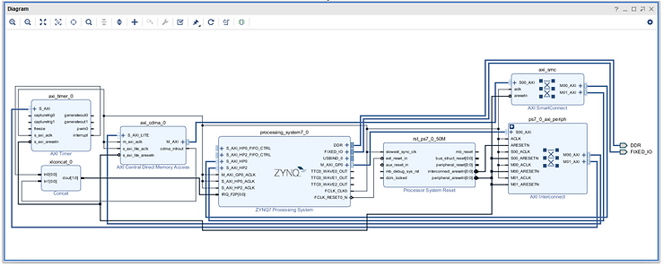
The completed diagram should now look as follows:
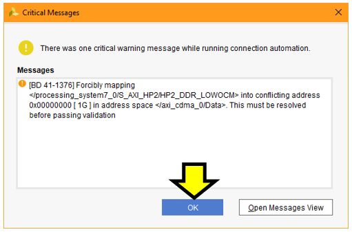
Step 2: Click OK to close the Critical Message. We will correct the address mapping in the next section.
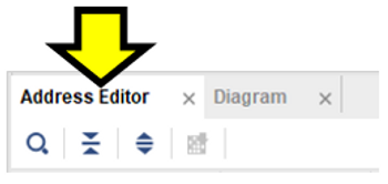
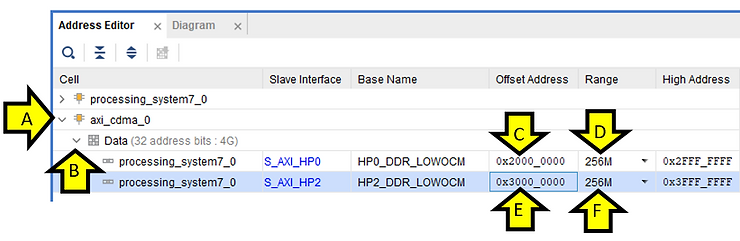
Part 8: Address configuration
Step 1: Select the Address Editor tab
Step 2: Adjust the high performance addresses
A: Expand axi_cdma_0
B: Expand Data
C: Adjust S_AXI_HP0 Offset Address to 0x2000_0000
D: Set S_AXI_HP0 Range to 256M
E: Adjust S_AXI_HP2 Offset Address to 0x3000_0000
F: Set S_AXI_HP2 Range to 256M
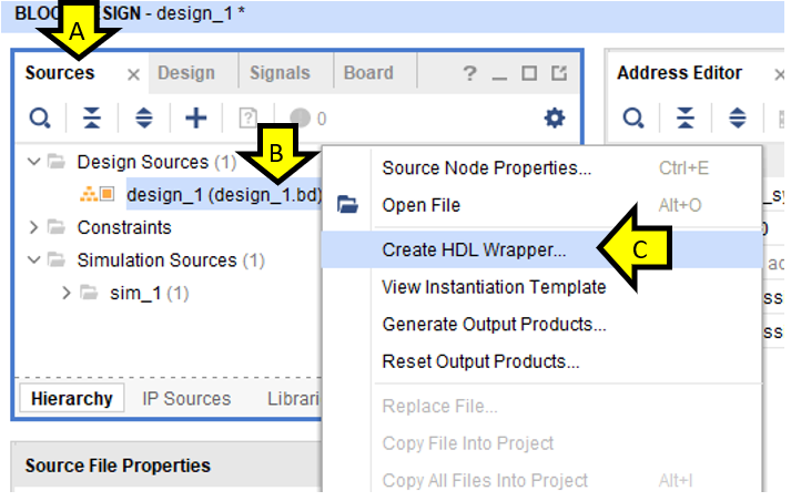
Part 9: Create a Top-Level HDL Wrapper
A. Click Sources
B. Right-click design_1 (design_1.bd) (1)
C. Click Create HDL Wrapper…
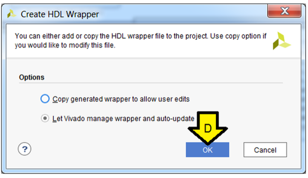
D. Leave Let Vivado manage wrapper and auto-update, click OK
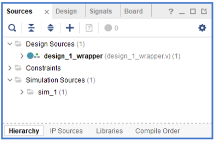
After a little time you should see:
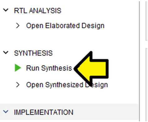
Part 10: Synthesize and Generate the Bitstream
Step 1: Click Run Synthesis
Step 2: Use defaults, click OK
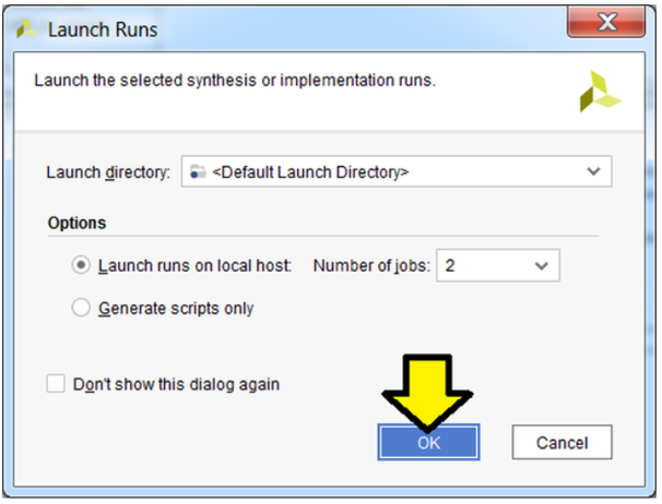
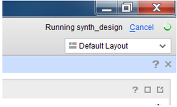
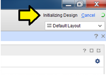
You’ll see the status in the upper right corner.
A sample of the output:
Step 3:
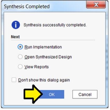
Wait approximately 10 min (using a custom built CPU with a Ryzen 5 2400G, M.2 SSD, and DDR4 Memory) until you see Synthesis Complete in the upper right corner…
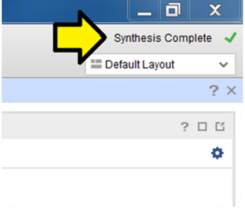
…and click OK to Run Implementation
Step 4: Use defaults, click OK
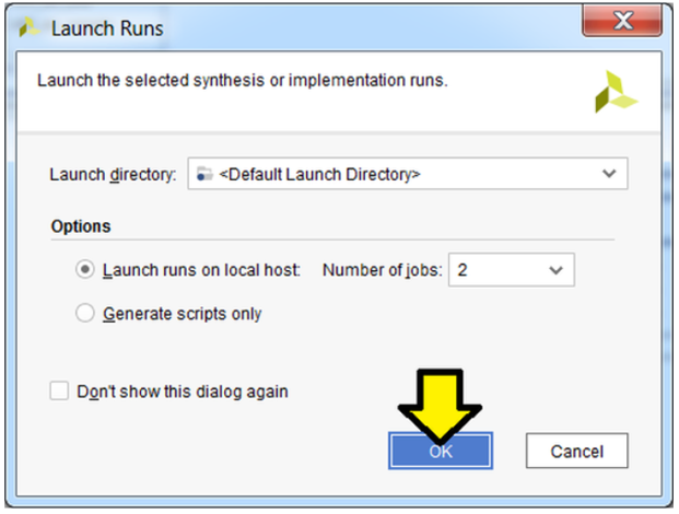
Again, you’ll see status in the upper right:
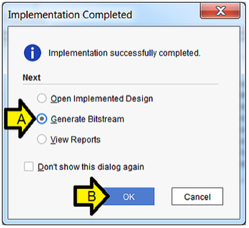
Step 5:
Wait approximately 10 min (using a custom built CPU with a Ryzen 5 2400G, M.2 SSD, and DDR4 Memory) until you see Implementation Complete in the upper right corner…
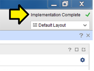
A. Select Generate Bitstream
B. Click OK
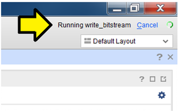
Step 6: Use defaults, click OK
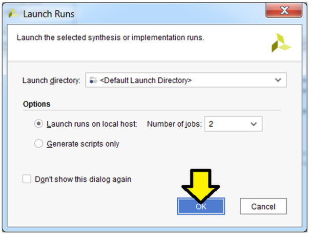
Again, you should see the status in the upper right:
Step 7: Click Cancel
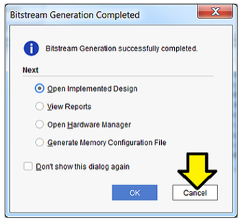
You may see this window pop-up:
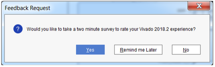
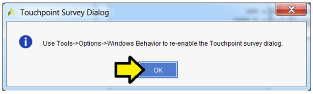
Feel free to send feedback, set a reminder or click No. If you click No you may see:
…click OK to dismiss.
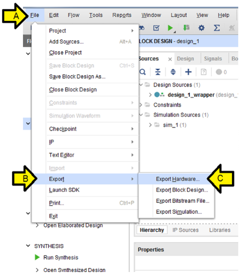
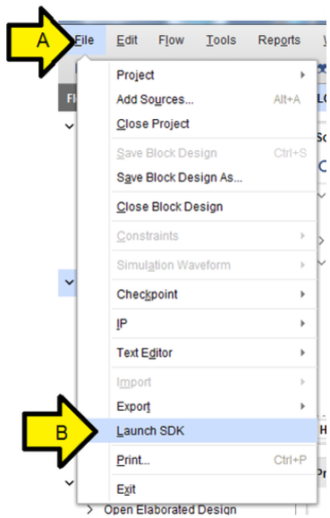
Part 11: Export the Design and Open the SDK
Step 1:
A. Click File
B. Click Export
C. Click Export Hardware…
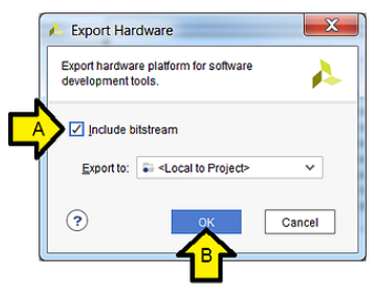
Step 2:
A. Click the Include bitstream checkbox
B. Click OK
Step 3:
A. Click File
B. Click Launch SDK
Note: you can open the workspace directly from the SDK by opening the SDK and specifying C:\vivadoprjs\cdmaslave\cdmaslave.sdk as the workspace.
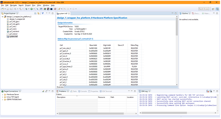
Step 4: Use defaults, click OK
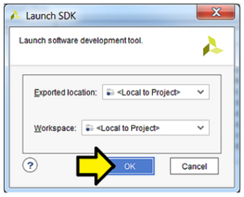
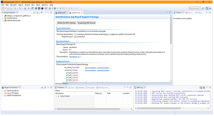
You should see:
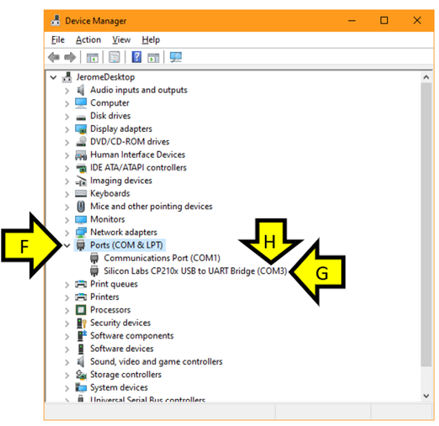
Part 12: Install the USB-to-UART Driver and Get the COM Assignment
Steps:
A. Goto [link] for the Silicon Labs CP210x USB to UART Bridge VCP Drivers
B. Download and unzip the correct installer for your OS
C. Install the driver (I did not need to restart on Windows 10 Professional)
D. Right-click the Windows Icon
E. Click Device Manager
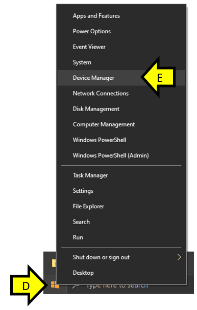
F. Expand the Ports (COM & LPT)
G. You should see Silicon Labs CP210x USB to UART Bridge
H. Note the COM port # (you’ll need this later)
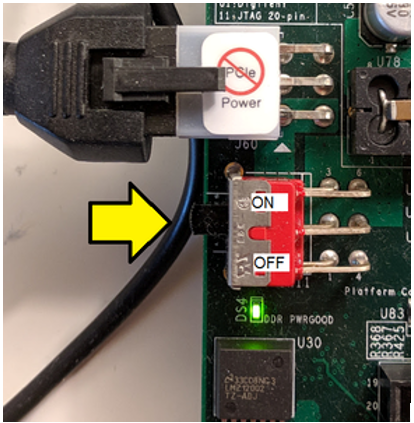
Part 13: Configure the Board to Boot from JTAG, Connect it to the PC and Power it On
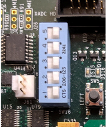
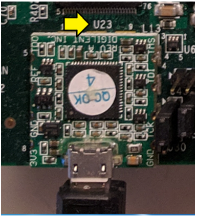
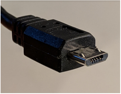
For the rest of the jumpers see the high-resolution photo of the board in the correct state at [link]. Step 2: Connect a Micro-B to Type-A (host connection) USB cable from U23 (Diglent USB JTAG interface) to the host PC
U23:
Micro-B connector:
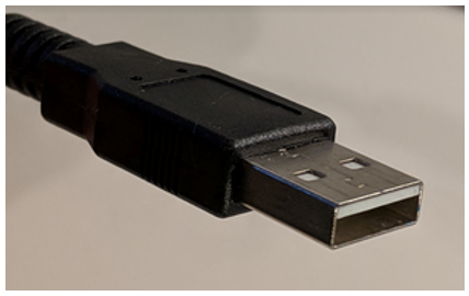
Type-A connector:
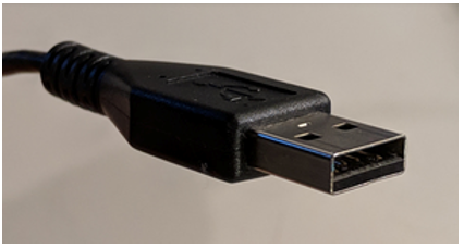
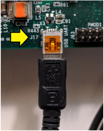
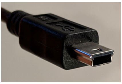
Step 3: Connect a Mini-B to Type-A (host connection) USB cable from J17 (CP2103GM USB-to_UART Bridge) to the host PC.
J17:
Mini-B connector:
Type-A connector:
Step 4: Turn on the board
Part 14: Create the Test App and BSP
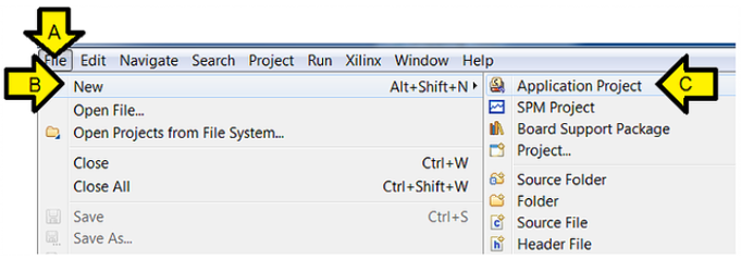
Step 1:
A. Click File
B. Click New
C. Click Application Project
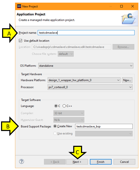
Step 2:
A. Type testcdmaslave into Project name:
B. Ensure the Board Support Package: Create New radio button is clicked and the name given is testcdmaslave_bsp
C. Click Next
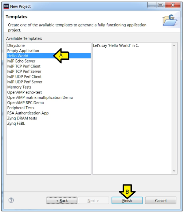
Step 3:
A. Click Hello World
B. Click Finish
You should see:
Part 15: Test Debug Run + Further Config
These instructions allow debugging to be set up more easily than entering the details manually. After running a debug session, the Debug Configuration is fixed up to reset the FPGA and program the bitstream. The debugger COM port is also configured so that output can be read and the steps to test it and see Hello World are listed.
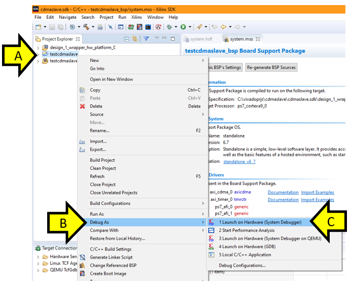
Step 1:
A. Right-click testcdmaslave
B. Click Debug As
C. Click Launch on Hardware (System Debugger)
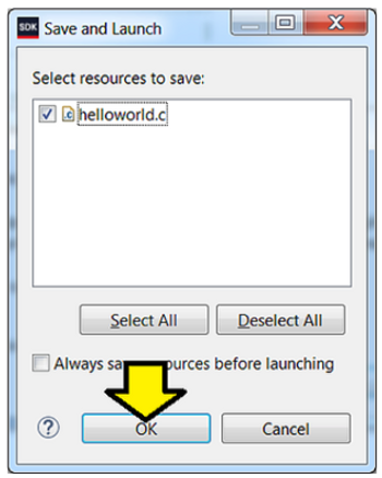
Step 2: Click OK (if you see this)
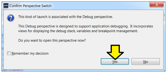
If you see this message click Yes. We’ll handle this in the next part.
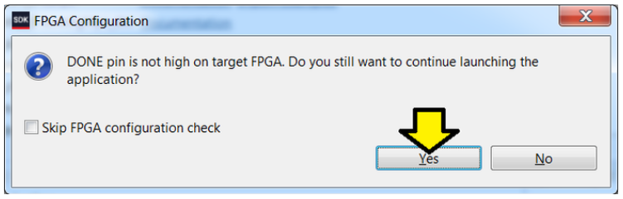
…click Yes.
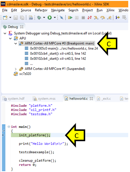
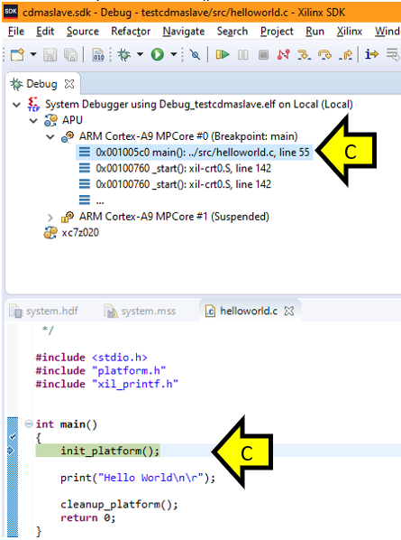
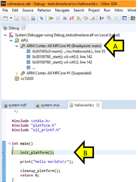
You should see the Debug Perspective display the code broken on init_platform():
A. Debug context on main()
B. helloworld.c on init_platform()
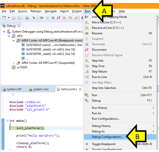
Step 3:
A. Click Run
B. Click Debug Configurations…
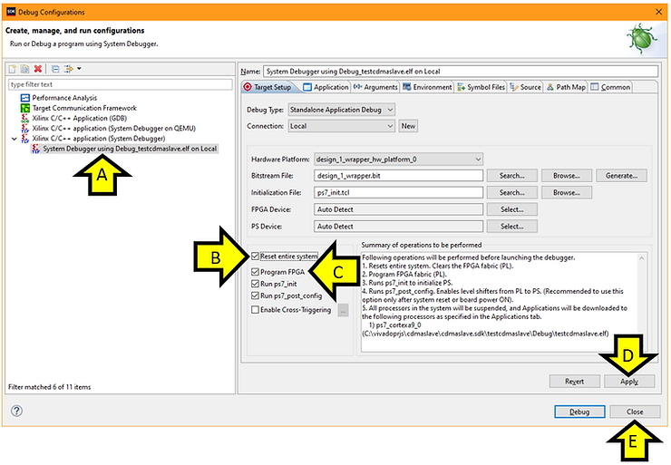
Step 4:
A. Ensure System Debugger using Debug_testaxislave on Local is selected (it should be)
B. Click the Reset entire system checkbox
C. Click the Program FPGA checkbox
D. Click Apply
E. Click Close
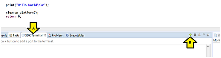
Step 5: Configure Debug View COM
A. Click SDK Terminal
B. Click the ’+’ (Connect to serial port.)
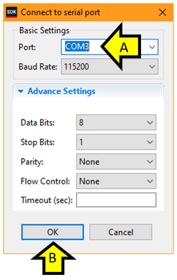
Step 6: Set Debug View COM settings
A. Enter the COM# from above
B. Click OK
You should see:
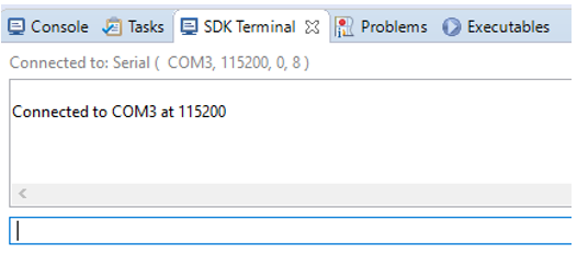
Step 7: Make sure you see Hello World on the console
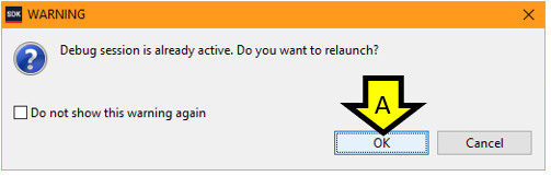
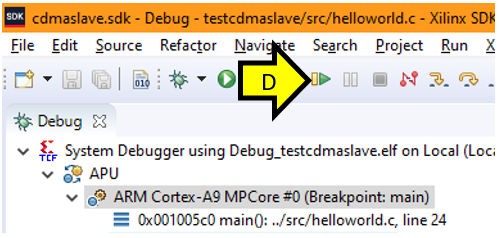
A. Click on the bug
![]()
B. Click OK
C. Wait for the system to hit the breakpoint on main()
D. Click Resume
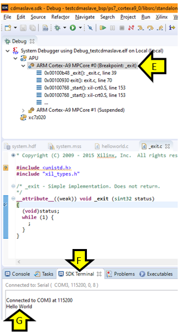
E. Wait until you see exit():
F. Click on SDK Terminal
G. Observe Hello World
Part 16: Test the CDMA Module
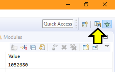
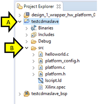
Step 1: Click on the C/C++ view
Step 2:
A. Expand testcdmaslave
B. Expand src
Step 3:
A. Right-click on src
B. Hover over New
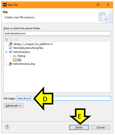
C. Click File
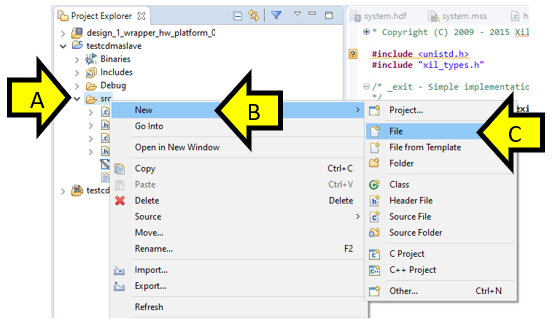
D. Type testcdma.c
E. Click Finish
F. Copy and paste the following code into testcdma.c. Note that this code comes directly from this [link] and has some minor modifications to conform with Linux Kernel Code Convention and to be able to use a header file in future steps.
/*
 * Copyright (c) 2015 Xilinx, Inc.  All rights reserved.
 *
 * Xilinx, Inc.
 * XILINX IS PROVIDING THIS DESIGN, CODE, OR INFORMATION "AS IS" AS A
 * COURTESY TO YOU.  BY PROVIDING THIS DESIGN, CODE, OR INFORMATION AS
 * ONE POSSIBLE   IMPLEMENTATION OF THIS FEATURE, APPLICATION OR
 * STANDARD, XILINX IS MAKING NO REPRESENTATION THAT THIS IMPLEMENTATION
 * IS FREE FROM ANY CLAIMS OF INFRINGEMENT, AND YOU ARE RESPONSIBLE
 * FOR OBTAINING ANY RIGHTS YOU MAY REQUIRE FOR YOUR IMPLEMENTATION.
 * XILINX EXPRESSLY DISCLAIMS ANY WARRANTY WHATSOEVER WITH RESPECT TO
 * THE ADEQUACY OF THE IMPLEMENTATION, INCLUDING BUT NOT LIMITED TO
 * ANY WARRANTIES OR REPRESENTATIONS THAT THIS IMPLEMENTATION IS FREE
 * FROM CLAIMS OF INFRINGEMENT, IMPLIED WARRANTIES OF MERCHANTABILITY
 * AND FITNESS FOR A PARTICULAR PURPOSE.
 *
 */

#include <stdio.h>
#include "xaxicdma.h"
#include "xdebug.h"
#include "xil_exception.h"
#include "xil_cache.h"
#include "xparameters.h"
#include "xscugic.h"

#define NUMBER_OF_TRANSFERS	2	/* Number of simple transfers to do */
#define DMA_CTRL_DEVICE_ID	XPAR_AXICDMA_0_DEVICE_ID
#define INTC_DEVICE_ID		XPAR_SCUGIC_SINGLE_DEVICE_ID
#define DMA_CTRL_IRPT_INTR	XPAR_FABRIC_AXI_CDMA_0_CDMA_INTROUT_INTR

static int Done;	/* Dma transfer is done */
static int Error;	/* Dma Bus Error occurs */

static u32 SourceAddr = 0x20000000;
static u32 DestAddr	= 0x30000000;

static XAxiCdma AxiCdmaInstance;	/* Instance of the XAxiCdma */
static XScuGic IntcController;	/* Instance of the Interrupt Controller */


//Array and 3 and 4 store data to be sent to DDR memory
static int Array_3[32][16];
static int Array_4[32][16];

//interemdiate stored data
static int Array_1[32][16];
static int Array_2[32][16];

//input seeds for psuedo random data
int const input[16] = {0xb504f33, 0xabeb4a0, 0xa267994, 0x987fbfc, 0x8e39d9c,
		0x839c3cc, 0x78ad74c, 0x6d743f4, 0x61f78a8, 0x563e6a8,
		0x4a5018c, 0x3e33f2c, 0x31f1704, 0x259020c, 0x1917a64,
		0xc8fb2c};
/* Length of the buffers for DMA transfer */
static u32 BUFFER_BYTESIZE	= (XPAR_AXI_CDMA_0_M_AXI_DATA_WIDTH
			* XPAR_AXI_CDMA_0_M_AXI_MAX_BURST_LEN);


static int CDMATransfer(XAxiCdma *InstancePtr, int Length, int Retries);

static void DisableIntrSystem(XScuGic *IntcInstancePtr, u32 IntrId)
{
		XScuGic_Disable(IntcInstancePtr, IntrId);
		XScuGic_Disconnect(IntcInstancePtr, IntrId);
}

//Multiply and Shift
int MUL_SHIFT_30(int x, int y)
{
	return ((int) (((long long) (x) * (y)) >> 30));
}


void MULT_SHIFT_LOOP(int Value)
{
	int i, j;

	for (i = 0; i < 32; i++) {
		for (j = 0; j < 16; j++) {
			Array_3[i][j] = (int)((MUL_SHIFT_30(input[j],
						Array_1[j][i])) + Value);
			Array_4[i][j] = (int)((MUL_SHIFT_30(input[j],
						Array_2[j][i])) + Value);
		}
	}
}

void TestPattern_Initialization(void)
{
	int i, j;

	for (i = 0; i < 32; i++) {
		for (j = 0; j < 16; j++) {
			Array_1[i][j] =  (int) ((0xA5A5A5A5 >> 1) * i);
			Array_2[i][j] =  (int) ((0xA5A5A5A5 << 1) * i);
		}
	}
}

/******************************************************************************
 *
 * Callback function for the simple transfer. It is called by the driver's
 * interrupt handler.
 *
 * @param	CallBackRef is the reference pointer registered through
 *		transfer submission. In this case, it is the pointer to the
 *		driver instance
 * @param	IrqMask is the interrupt mask the driver interrupt handler
 *		passes to the callback function.
 * @param	IgnorePtr is a pointer that is ignored by simple callback
 *		function
 *
 * @return	None
 *
 * @note		None
 *
 *****************************************************************************/
static void Cdma_CallBack(void *CallBackRef, u32 IrqMask, int *IgnorePtr)
{

	if (IrqMask & XAXICDMA_XR_IRQ_ERROR_MASK) {
		Error = TRUE;
		printf("--- Transfer Error --- \r\n");
	}

	if (IrqMask & XAXICDMA_XR_IRQ_IOC_MASK) {
		printf("--- Transfer Done --- \r\n");
		Done = TRUE;
	}

}

static int SetupIntrSystem(XScuGic *IntcInstancePtr, XAxiCdma *InstancePtr,
		u32 IntrId)
{
	int Status;


	/*
	 * Initialize the interrupt controller driver
	 */
	XScuGic_Config *IntcConfig;


	/*
	 * Initialize the interrupt controller driver so that it is ready to
	 * use.
	 */
	IntcConfig = XScuGic_LookupConfig(INTC_DEVICE_ID);
	if (IntcConfig == NULL)
		return XST_FAILURE;

	Status = XScuGic_CfgInitialize(IntcInstancePtr, IntcConfig,
					IntcConfig->CpuBaseAddress);
	if (Status != XST_SUCCESS)
		return XST_FAILURE;

	XScuGic_SetPriorityTriggerType(IntcInstancePtr, IntrId, 0xA0, 0x3);

	/*
	 * Connect the device driver handler that will be called when an
	 * interrupt for the device occurs, the handler defined above performs
	 * the specific interrupt processing for the device.
	 */
	Status = XScuGic_Connect(IntcInstancePtr, IntrId,
				(Xil_InterruptHandler)XAxiCdma_IntrHandler,
				InstancePtr);

	if (Status != XST_SUCCESS)
		return Status;

	/*
	 * Enable the interrupt for the DMA device.
	 */
	XScuGic_Enable(IntcInstancePtr, IntrId);


	Xil_ExceptionInit();

	/*
	 * Connect the interrupt controller interrupt handler to the hardware
	 * interrupt handling logic in the processor.
	 */
	Xil_ExceptionRegisterHandler(XIL_EXCEPTION_ID_IRQ_INT,
				(Xil_ExceptionHandler)XScuGic_InterruptHandler,
				IntcInstancePtr);


	/*
	 * Enable interrupts in the Processor.
	 */
	Xil_ExceptionEnable();


	return XST_SUCCESS;
}


int XAxiCdma_Interrupt(XScuGic *IntcInstancePtr, XAxiCdma *InstancePtr,
		u16 DeviceId, u32 IntrId)
{
	XAxiCdma_Config *CfgPtr;
	int Status;
	int SubmitTries = 1;		/* Retry to submit */
	int Tries = NUMBER_OF_TRANSFERS;
	int Index;

	/* Initialize the XAxiCdma device. */
	CfgPtr = XAxiCdma_LookupConfig(DeviceId);
	if (!CfgPtr)
		return XST_FAILURE;

	Status = XAxiCdma_CfgInitialize(InstancePtr,
			CfgPtr,
			CfgPtr->BaseAddress);
	if (Status != XST_SUCCESS)
		return XST_FAILURE;

	/* Setup the interrupt system */
	Status = SetupIntrSystem(IntcInstancePtr, InstancePtr, IntrId);
	if (Status != XST_SUCCESS)
		return XST_FAILURE;

	/* Enable all (completion/error/delay) interrupts */
	XAxiCdma_IntrEnable(InstancePtr, XAXICDMA_XR_IRQ_ALL_MASK);

	for (Index = 0; Index < Tries; Index++) {
		Status = CDMATransfer(InstancePtr,
			   BUFFER_BYTESIZE, SubmitTries);

		if (Status != XST_SUCCESS) {
			DisableIntrSystem(IntcInstancePtr, IntrId);
			return XST_FAILURE;
		}
	}

	/* Test finishes successfully, clean up and return */
	DisableIntrSystem(IntcInstancePtr, IntrId);

	return XST_SUCCESS;
}

/******************************************************************************
 *
 *
 * This function does CDMA transfer
 *
 * @param	InstancePtr is a pointer to the XAxiCdma instance
 * @param	Length is the transfer length
 * @param	Retries is how many times to retry on submission
 *
 * @return
 *		- XST_SUCCESS if transfer is successful
 *		- XST_FAILURE if either the transfer fails or the data has
 *		  error
 *
 * @note	None
 *
 *****************************************************************************/
static int CDMATransfer(XAxiCdma *InstancePtr, int Length, int Retries)
{
	int Status;

	printf("Start Transfer \r\n");

	/* Try to start the DMA transfer */
	Done = FALSE;
	Error = FALSE;

	/* Flush the SrcBuffer before the DMA transfer, in case the Data Cache
	 *	is enabled
	 */
	Xil_DCacheFlushRange((u32)SourceAddr, Length);

	Status = XAxiCdma_SimpleTransfer(InstancePtr,
				(u32)(u8 *) (SourceAddr),
				(u32)(DestAddr),
				Length,
				Cdma_CallBack,
				(void *)InstancePtr);

	if (Status == XST_FAILURE) {
		printf("Error in Transfer  \r\n");
		return 1;
	}

	/* Wait until the DMA transfer is done */
	while (!Done && !Error)
		;

	if (Error) {
		return XST_FAILURE;
		return 1;
	}


	/* Invalidate the DestBuffer before receiving the data, in case the
	 * Data Cache is enabled
	 */
	Xil_DCacheInvalidateRange((u32)DestAddr, Length);

	return XST_SUCCESS;
}


int testcdmaexample(void)
{
	int Status;
	u32 *SrcPtr;
	u32 *DestPtr;
	unsigned int  Index;
	int i, j;

	printf("--- Entering %s --- \r\n", __func__);

	/**********************************************************************
	 * Step : 1 :	Initialization of the Source Memory with the Specified
	 *			test pattern
	 *		Clear Destination memory
	 *********************************************************************/
	TestPattern_Initialization();

	/* Initialize the source buffer bytes with a pattern and the
	 * destination buffer bytes to zero
	 */
	SrcPtr = (u32 *)SourceAddr;
	DestPtr = (u32 *)DestAddr;
	for (Index = 0; Index < (BUFFER_BYTESIZE/1024); Index++) {
		MULT_SHIFT_LOOP((Index*100));
		for (i = 0; i < 32; i++) {
			for (j = 0; j < 16; j++) {
				SrcPtr[((i+j))*(Index+1)]	= Array_3[i][j];
				SrcPtr[((i+j)*(Index+1)) + 1]	= Array_4[i][j];
				DestPtr[(i+j)*(Index+1)]	= 0;
				DestPtr[((i+j)*(Index+1)) + 1]	= 0;
			}
		}
	}

	/**********************************************************************
	 * Step : 2 :	AXI CDMA Initialization
	 *		Association of the CDMA ISR with the Interrupt
	 *		Enable the CDMA Interrupt
	 *		Provide Source and destination location to CDMA
	 *		Specified Number of byte to be transfer to CDMA
	 *			register
	 *		Start the CDMA
	 *		Wait for the Interrupt and return the status
	 *********************************************************************/

	Status = XAxiCdma_Interrupt(&IntcController,
					&AxiCdmaInstance,
					DMA_CTRL_DEVICE_ID,
					DMA_CTRL_IRPT_INTR);

	if (Status != XST_SUCCESS) {
		printf("XAxiCdma_Interrupt: Failed\r\n");
		return XST_FAILURE;
	}

	xil_printf("XAxiCdma_Interrupt: Passed\r\n");


	/**********************************************************************
	 * Step : 3 :	Compare Source memory with Destination memory
	 *		Return the Status
	 *********************************************************************/
	for (Index = 0; Index < (BUFFER_BYTESIZE/4); Index++) {
		if (DestPtr[Index] != SrcPtr[Index]) {
			printf("Error in Comparison : Index : %x \r\n", Index);
			return XST_FAILURE;
		}
	}

	printf("DMA Transfer is Successful \r\n");
	return XST_SUCCESS;
}
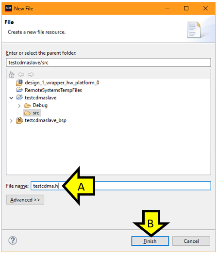
Step 4:
A. Right-click on src
B. Hover over New
C. Click File
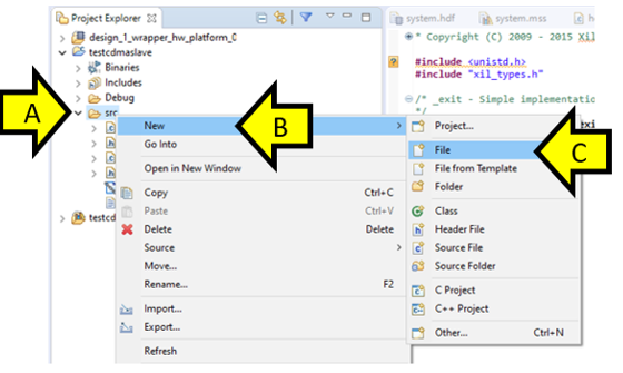
Step 5:
A. Type testcdma.h
B. Click Finish
Step 6: Copy and paste the following code into testexample.h
int testcdmaexample(void);
Step 9: Update helloworld.c
A. Double-click helloworld.c
B. Add #include “testcdma.h” as shown
C. Add testcdmaexample(); as shown
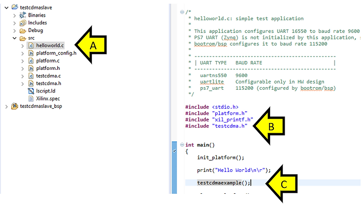
D. Click save-all
![]()
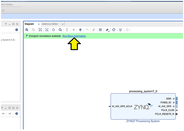
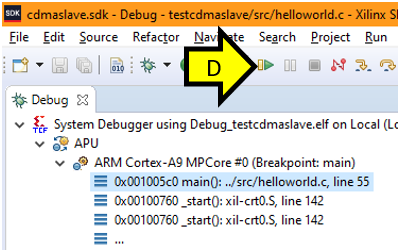
Step 7: Run it
A. Click on the bug
![]()
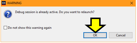
If you see WARNING pop-up this click OK
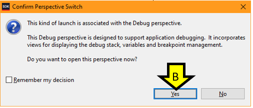
B. Click Yes to confirm the switch to the Debug perspective
C. You should see execution stopped at main(
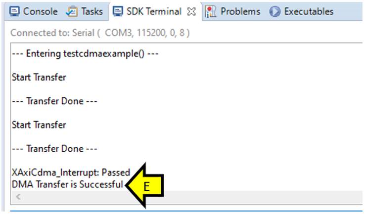
D. Click Resume
E. You should see that the DMA transfer was successful.
References
· Zynq-7000 All Programable SoC: Embedded Design Tutorial [link]
· Xilinx Design Files [link]