
Zynq-7000 + AXI Slave Hello World
![]()
This post shows how to create a Xilinx Zynq-7000 + AXI slave in Vivado 2018.2 and read/write the AXI slave from the ARM9 of the Zynq-7000 using bare-metal code built with the SDK on the ZC702.
Versions Used
Xilinx Vivado 2018.2 & SDK 2018.2
ZC702 Rev 1.1
Windows 7 SP1
Before you Start
Review ZC702 JTAG and serial port set up instructions @ [link]. These instructions are also reviewed below.
Contents
Part 1: Create the Vivado Project
Part 2: Create the AXI Slave IP and Add it to the Repo
Part 3: Create the Zynq-7000 in IP Integrator
Part 4: Connect the AXI Slave
Part 5: Build the Bitstream (to Program the FPGA)
Part 6: Export the Design and Open the SDK
Part 7: Install the USB-to-UART Driver and Get the COM Assignment
Part 8: Configure the Board to Boot from JTAG, Connect it to the PC and Power it On
Part 9: Create the Test App and BSP
Part 10: Test Debug Run + Further Config
Part 11: Test the AXI module
Part 1: Create the Vivado Project
Step 1: Start Vivado
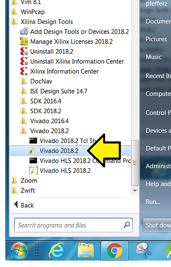
Step 2: Click Create Project
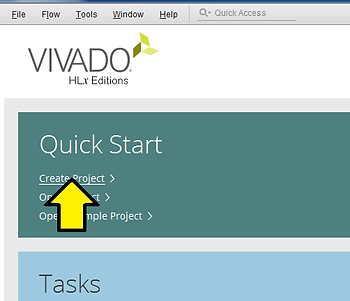
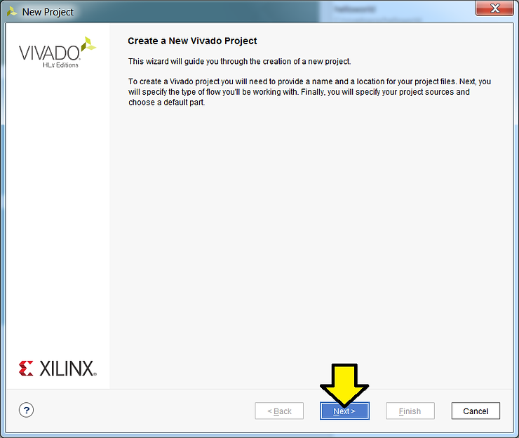
Step 3: Click Next
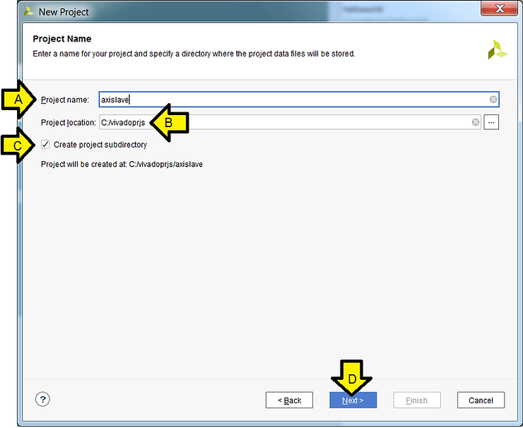
Step 4:
A. Set Project name to axislave
B: Set Project location to C:/vivadoprjs (create C:/vivadoprjs if it doesn’t exist)
C. Click the Create project subdirectory checkbox
D. Click Next
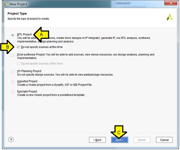
Step 5:
A. Select RTL Project
B. Check the Do not specify sources at this time check box
C. Click Next
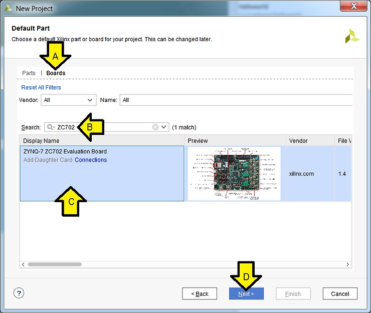
Step 6:
A. Click Boards
B. Type ZC702
C. Click on the ZYNQ-7 ZC702 Evaluation Board box
D. Click Next
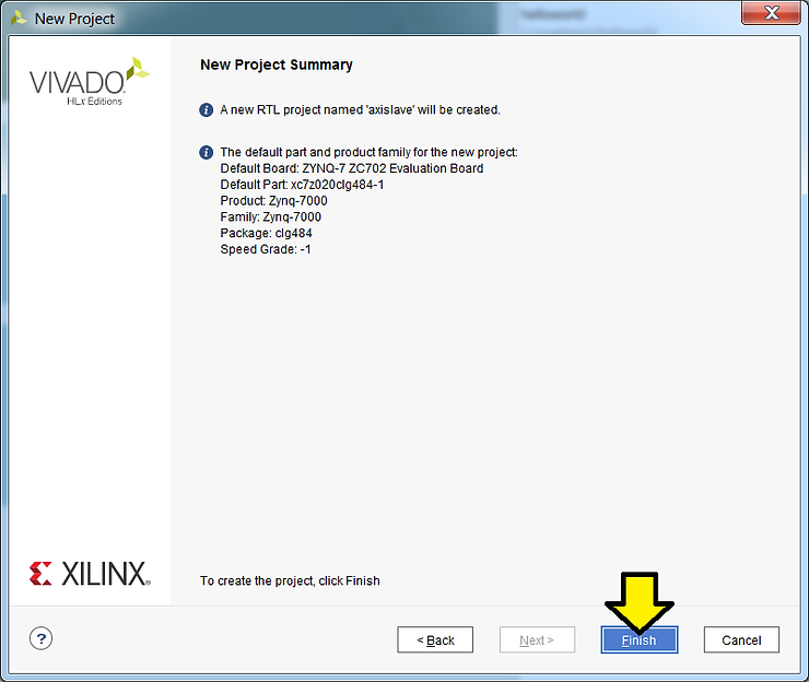
Step 7: Click Finish
Part 2: Create the AXI Slave IP and Add it to the Repo
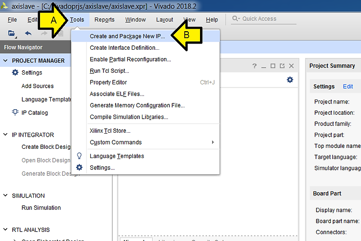
Step 1:
A. Click Tools
B. Click Create and Package New IP…
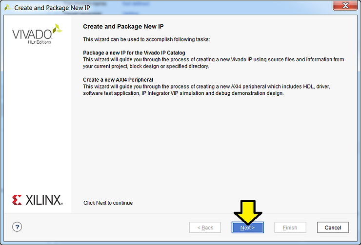
Step 2: Click Next
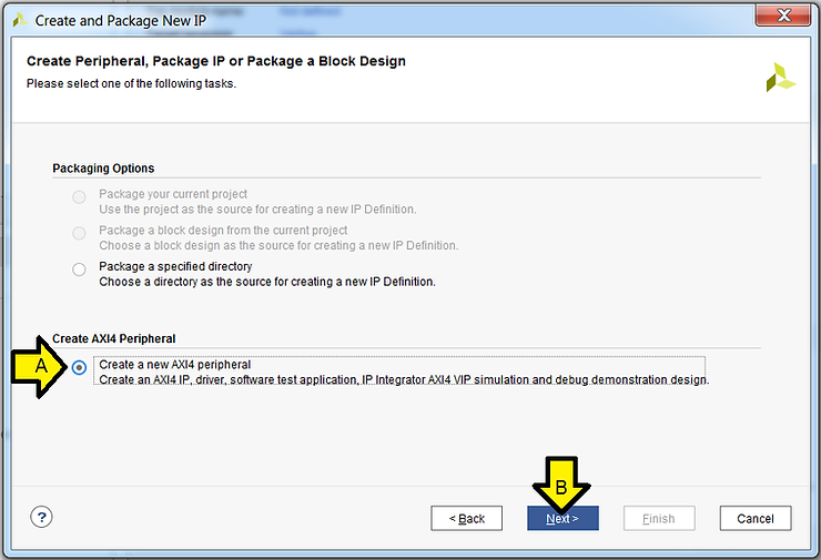
Step 3:
A. Select Create a new AXI4 peripheral
B. Click Next
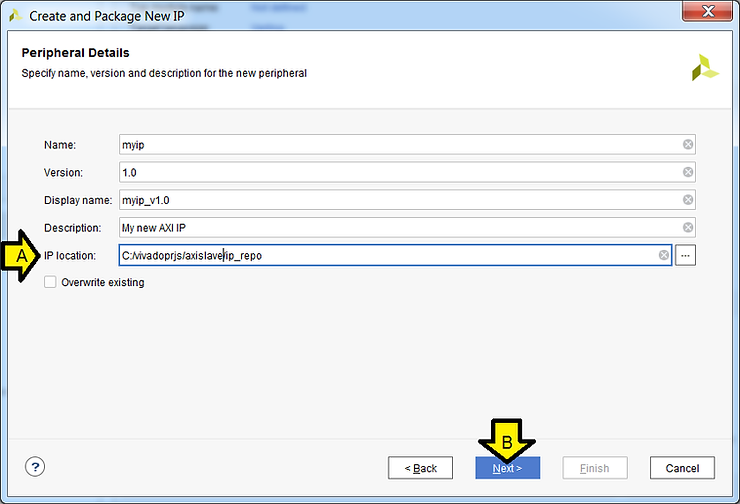
Step 4:
A. Use defaults except, set IP location to: C:/vivadoprjs/axislave/ip_repo
B. Click Next
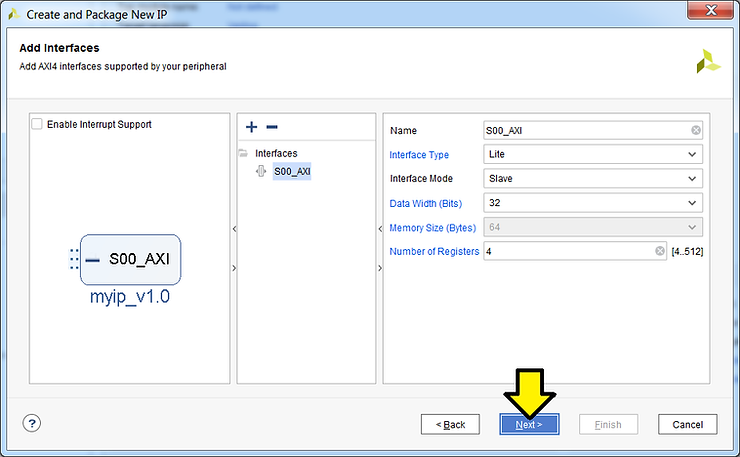
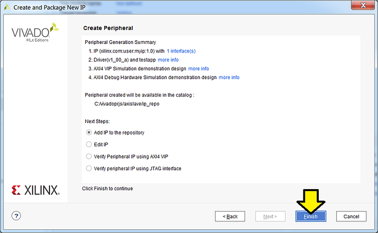
Step 5: Use defaults, click Next
Step 6: Use defaults, click Finish
Part 3: Create the Zynq-7000 in IP Integrator
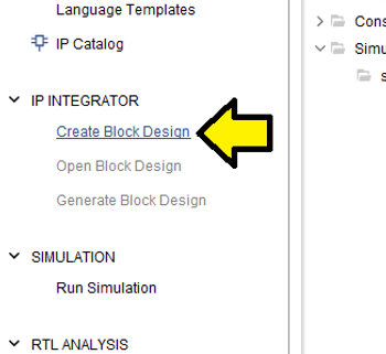
Step 1: Click Create Block Design
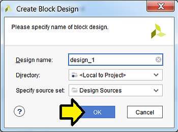
Step 2: Use defaults, click OK
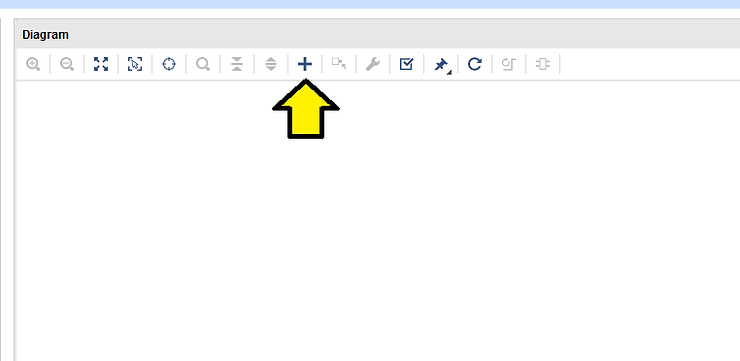
Step 3: Click +
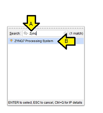
Step 4:
A. Type Zynq
B. Double-click on ZYNQ7 Processing System
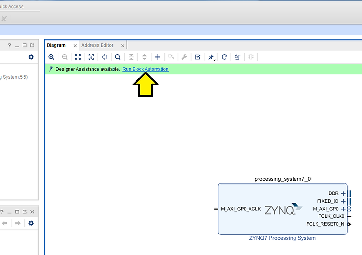
Step 5: Click Run Block Automation
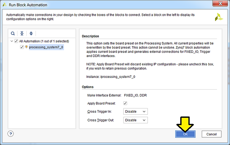
Step 6: Use defaults, click OK
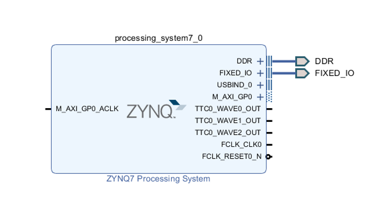
You should see:
Part 4: Connect the AXI Slave
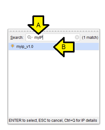
Step 1: Click +
Step 2:
A. Type myIP
B. Double-click myip_v1.0
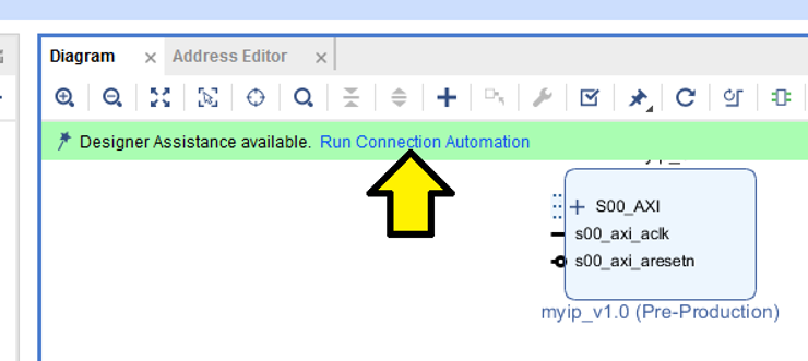
Step 3: Click Run Connection Automation
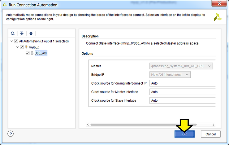
Step 4: Use defaults, click OK
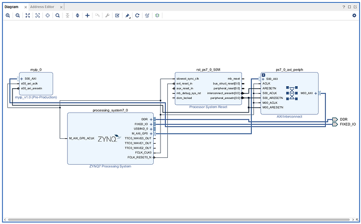
You should see:
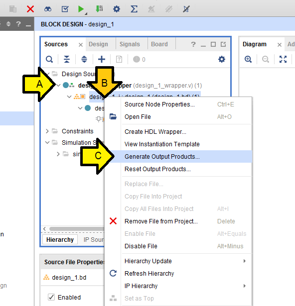
Step 5: Click Sources
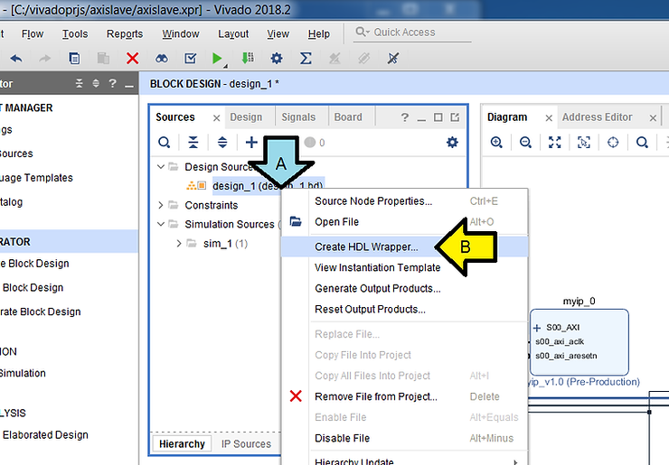
Step 6:
A. Right-click design_1 (design_1.bd)
B. Click Create HDL Wrapper…
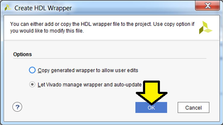
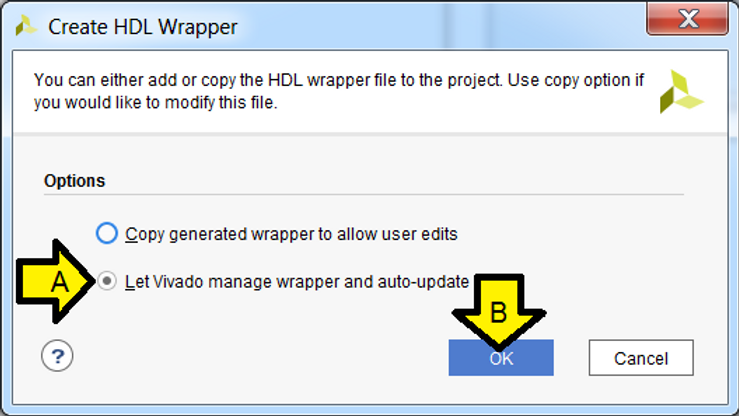
Step 7: Use default, click OK
You should see:
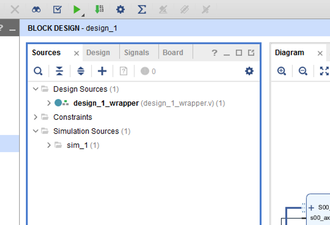
Step 8:
A. Click to expand design_1_wrapper (design_1_wrapper.v)(1)
B. Right-click on design_1_i: design_1 (design_1.bd)(1)
C. Click Generate Output Products…
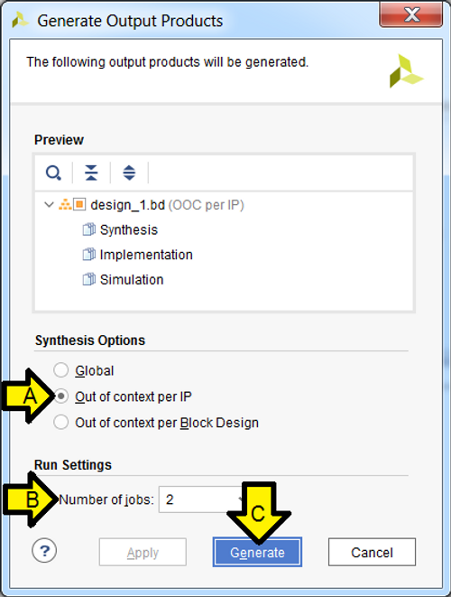
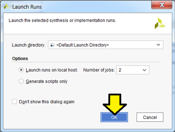
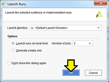
Step 7:
A. Leave selected or select Out of context per IP
B. Leave Number of jobs at 2
C. Click Generate
Step 8: Click OK and let the operation complete
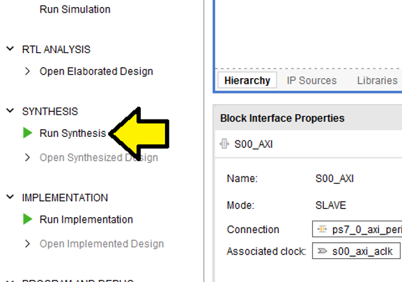
Part 5: Build the Bitstream (to Program the FPGA)
Step 1: Click Run Synthesis
Step 2: Use defaults, click OK
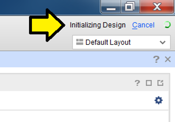
You’ll see the status in the upper right corner:
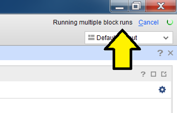
Step 3:
Wait approximately 1 to 5 min until you see Synthesis Complete in the upper right corner…
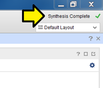
…and click OK to Run Implementation:
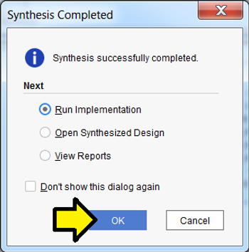
Step 4: Use defaults, click OK
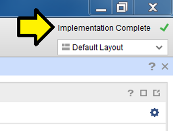
Again, you’ll see status in the upper right:
Step 5:
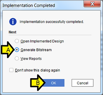
Wait approximately 1 to 5 min until you see Implementation Complete in the upper right corner…
A. Select Generate Bitstream
B. Click OK
Step 6: Use defaults, click OK
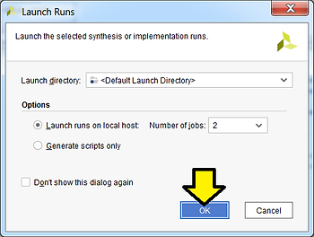
Again, you should see the status in the upper right:
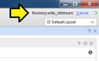
Step 7: Click Cancel
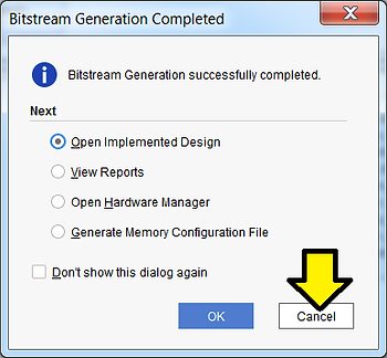
You may see this window pop-up:
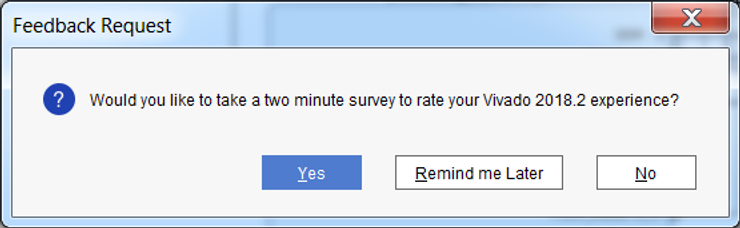
Feel free to send feedback, set a reminder or click No. If you click No you may see:
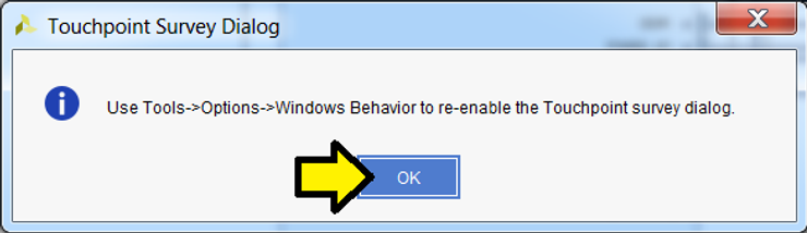
…click OK to dismiss.
Part 6: Export the Design and Open the SDK
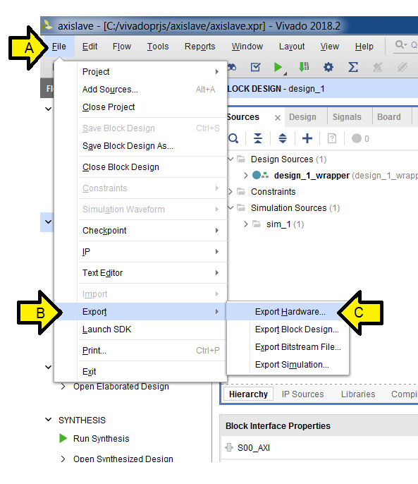
Step 1:
A. Click File
B. Click Export
C. Click Export Hardware…
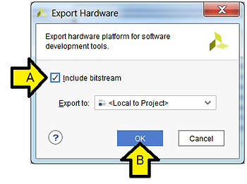
Step 2:
A. Click the Include bitstream checkbox
B. Click OK
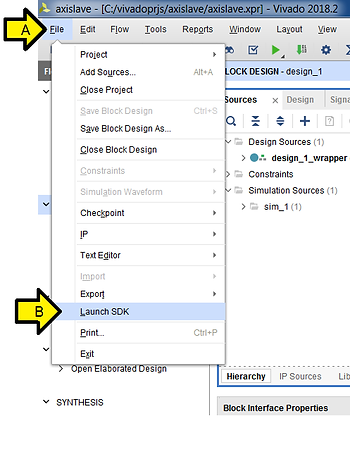
Step 3:
A. Click File
B. Click Launch SDK
Note: you can open up the workspace from the SDK by launching the SDK and selecting C:\vivadoprjs\axislave\axislave.sdk as the workspace.
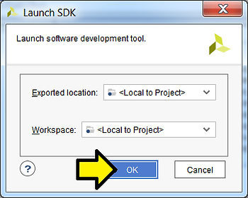
Step 4: Use defaults, click OK
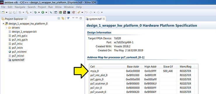
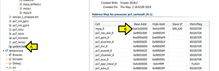
Step 5: After the SDK launches, note the Base Addr of myip_0:
Part 7: Install the USB-to-UART Driver and Get the COM Assignment
Steps:
A. Goto [link] for the Silicon Labs CP210x USB to UART Bridge VCP Drivers
B. Download and unzip the correct installer for your OS
C. Install the driver (I did not need to restart on Windows 7 SP1)
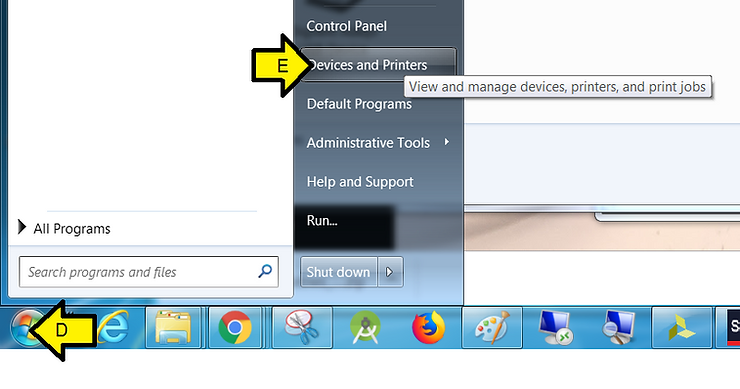
D. Click Windows
E. Click Devices and Printers
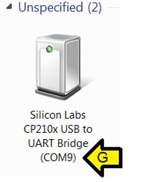
F. You should see Silicon Labs CP210x USB to UART BridgeG. Note the COM port (you’ll need this later)
Part 8: Configure the Board to Boot from JTAG, Connect it to the PC and Power it On
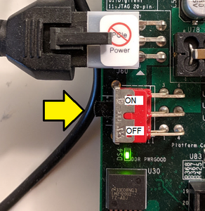
Step 1: Set SW16 to JTAG mode [mode documentation see p.16]
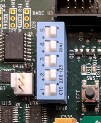
For the rest of the jumpers see the high-resolution photo of the board in the correct state at [link]. Step 2: Connect a Micro-B to Type-A (host connection) USB cable from U23 (Diglent USB JTAG interface) to the host PC
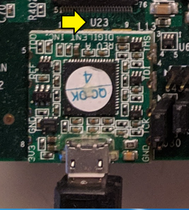
Step 2: Connect a Micro-B to Type-A (host connection) USB cable from U23 (Diglent USB JTAG interface) to the host PC
U23:
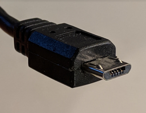
Micro-B connector:
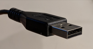
Type-A connector:
Step 3: Connect a Mini-B to Type-A (host connection) USB cable from J17 (CP2103GM USB-to_UART Bridge) to the host PC.
J17:
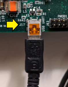
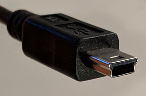
Mini-B connector:
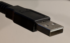
Type-A connector:
Step 4: Turn on the board
Part 9: Create the Test App and BSP
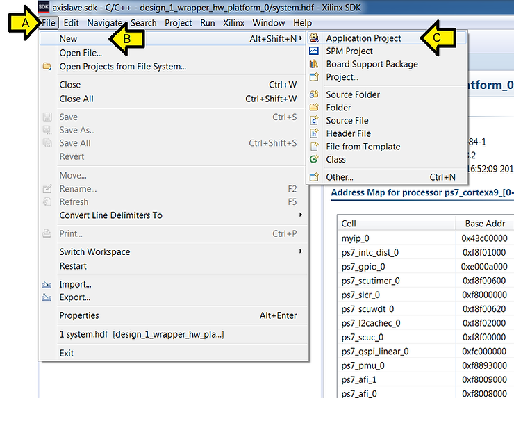
Step 1:
A. Click File
B. Click New
C. Click Application Project
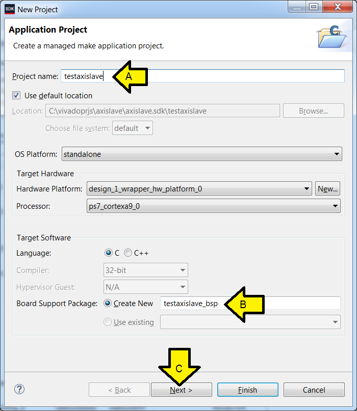
Step 2:
A. Type testaxislave
B. Ensure the Board Support Package: Create New radio button is clicked and the name given is testaxislave_bsp
C. Click Next
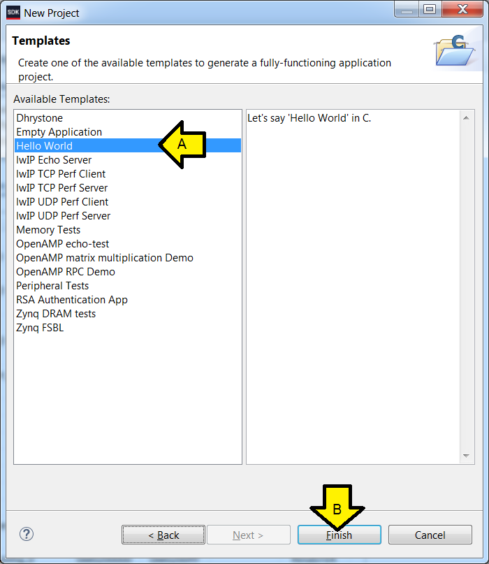
Step 3:
A. Click Hello World
B. Click Finish
Part 10: Test Debug Run + Further Config
These instructions allow debug to be set up more easily than entering in the details manually. After running a debug session, the Debug Configuration is fixed up to reset the FPGA and program the bitstream. The debugger COM port is also configured so that output can be read and the steps to test it and see Hello World are listed.
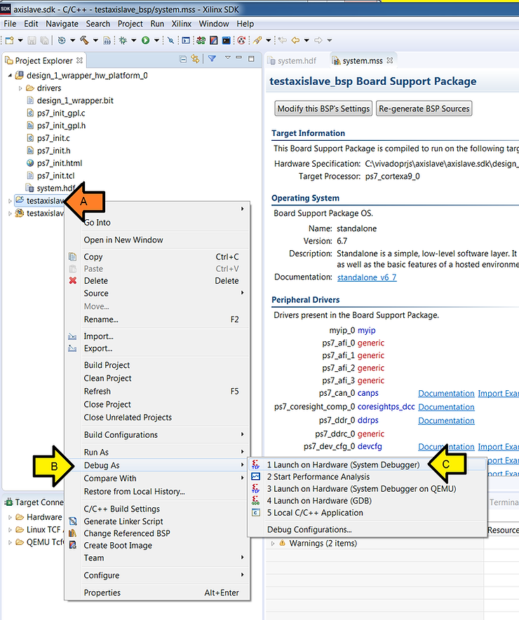
Step 1:
A. Right-click testaxislave
B. Click Debug As
C. Click Launch on Hardware (System Debugger)
Step 2: Click OK
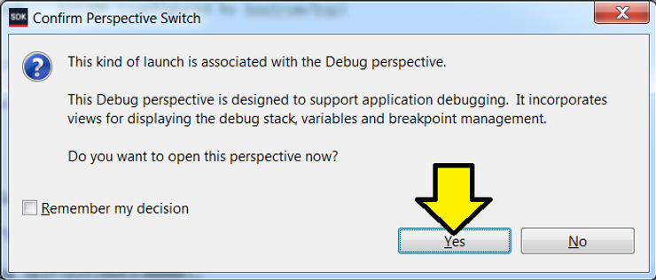
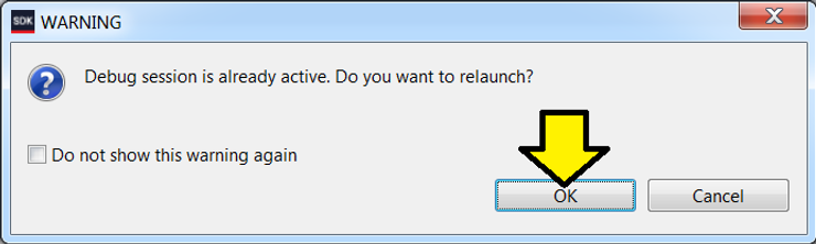
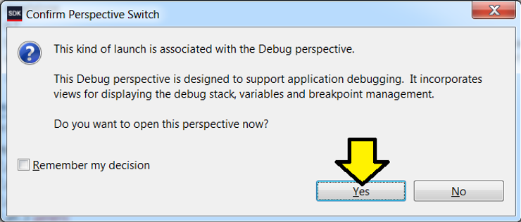
If you see this message click Yes. We’ll handle this in the next part.
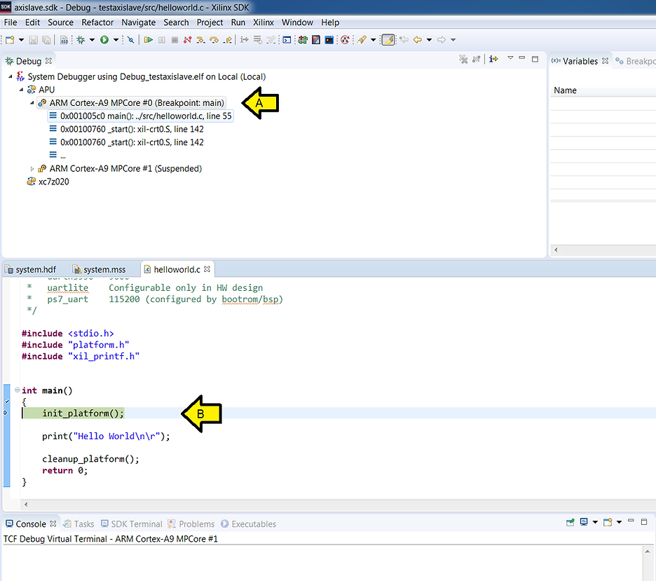
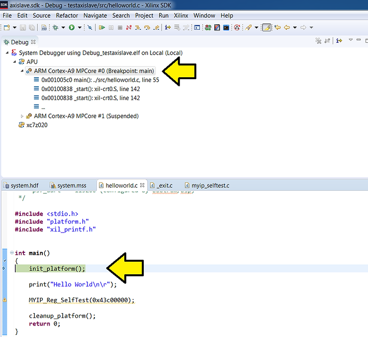
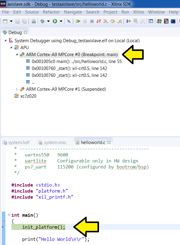
You should see the Debug Perspective display the code broken on init_platform():
A. Debug context on main()
B. helloworld.c on init_platform()
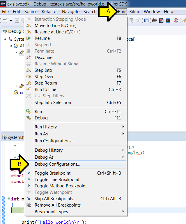
Step 3:
A. Click Run
B. Click Debug Configurations…
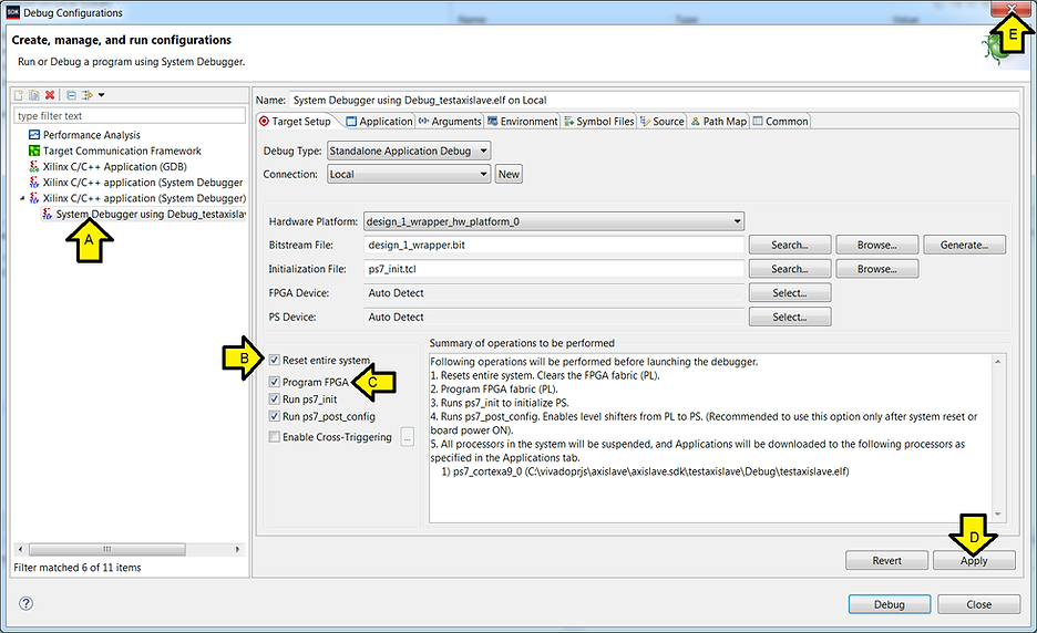
Step 4:
A. Ensure System Debugger using Debug_testaxislave is selected (it should be)
B. Click the Reset entire system checkbox
C. Click the Program FPGA checkbox
D. Click Apply
E. Click Close
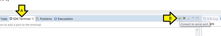
Step 5: Configure Debug View COM
A. Click SDK Terminal
B. Click the ’+’ (Connect to serial port.)
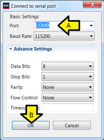
Step 6: Set Debug View COM settings
A. Enter the COM# from above
B. Click OK
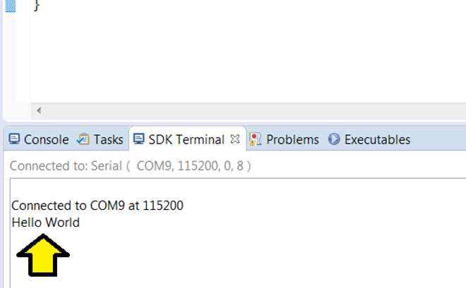
Step 7: Make sure you see Hello World on the console
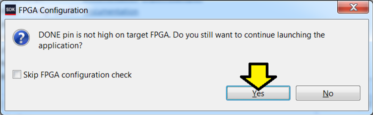
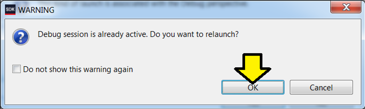
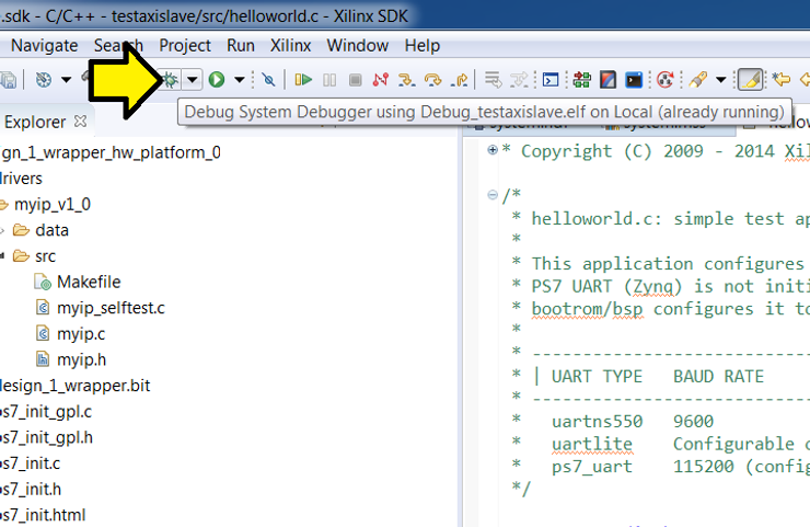
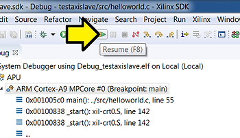
Click on the bug
![]()
Step 8: Click OK
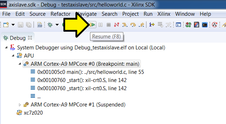
Step 9: Wait for the system to hit the breakpoint on main()
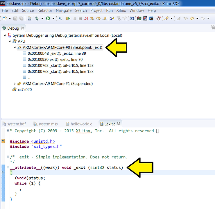
Step 10: Click Resume
…and wait until you see exit():
Step 11: Click on SDK Terminal…
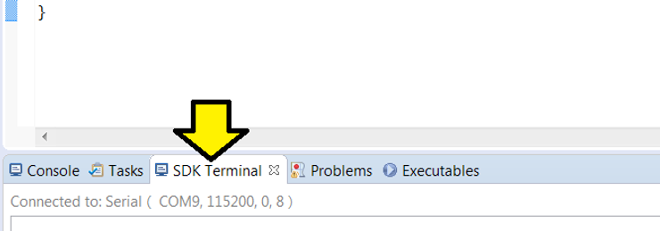
…to see Hello World:
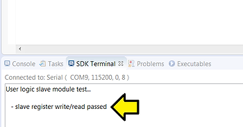
Part 11: Test the AXI module
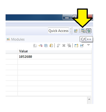
Step 1: Click on the C/C++ view
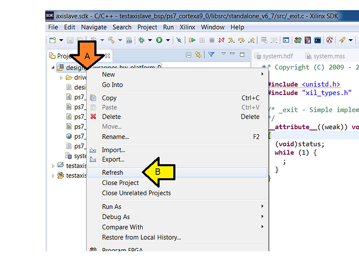
Step 2: Show myip tests
A. Right-click on design_1_wrapper_hw_platform
B. Click Refresh
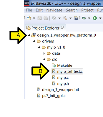
Step 3:
A. Expand design_1_wrapper_hw_platform, drivers, myip_v1_0, src
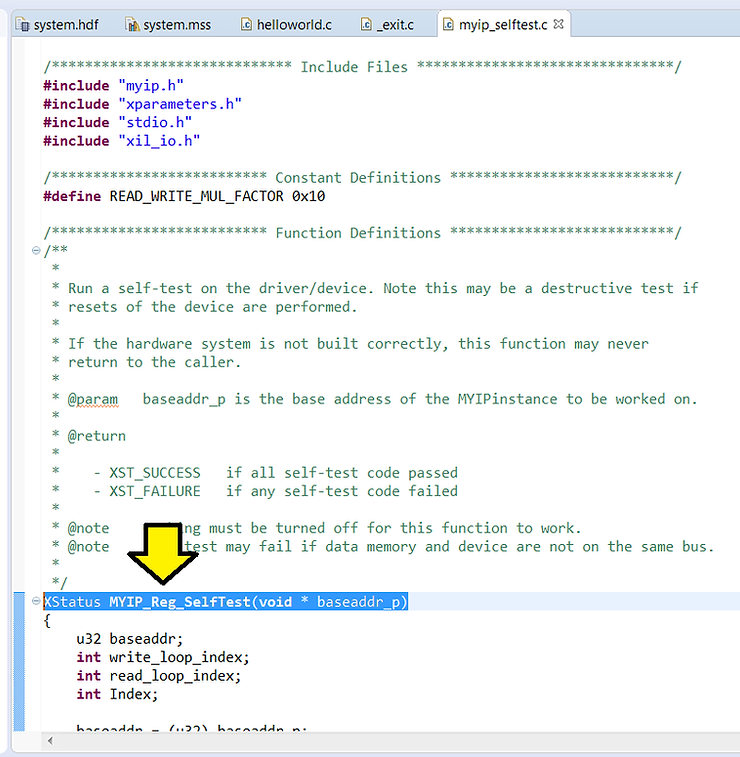
B. Double click on myip_selftest.c
Step 4: Select XStatus MYIP_Reg_SelfTest(void * baseaddr_p)
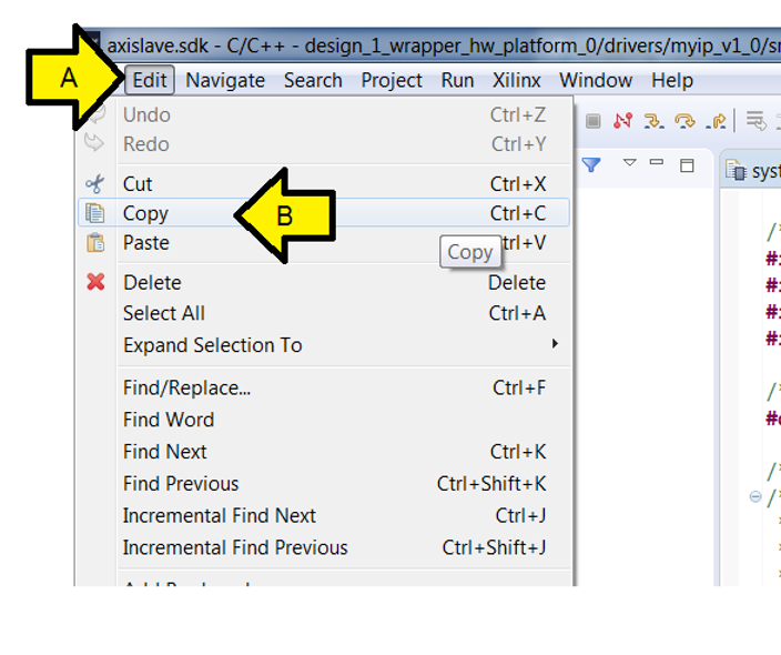
Step 5:
A. Click Edit
B. Click Copy
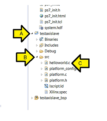
Step 6:
A. Expand testaxislave
B. Expand src
C. Double-click helloworld.c
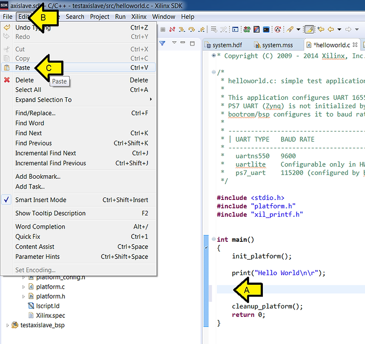
Step 7:
A. Press ENTER to make room
B. Click Edit
C. Click Paste
Step 8: Get the base address of myip_0
A. Double-click the system.hdf file
B. Note the address (it won’t let you copy-paste it)
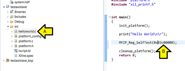
Step 9:
A. Double-click on helloworld.c
B. Fix up the code so it reads: MYIP_Reg_SelfTest(0x43c00000);
Step 10: Click the bug to restart debugging
Step 11: Click OK
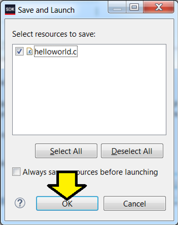
Step 12: Click OK
Step 13: Click Yes
You should see the code stopped at the breakpoint on main()
Step 14: Click Resume
You should see:
References
- Xilinx logo found via https://twitter.com/xilinxinc at [link]