
Light Up ZC706 LEDs Using Push Buttons with VHDL
![]()
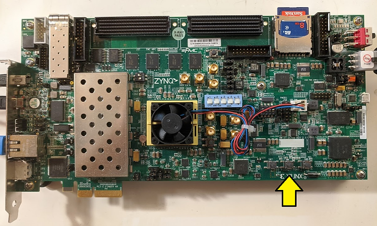
This post shows how to use VHDL to connect SW7, SW9 and SW8 to LCR PL GPIO LEDS using VHDL.
This post picks up right after [link].
Prerequisites
This post assumes Vivado 2018.2 and the Digilent cable drivers have been installed.
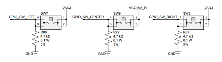
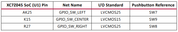
Push Buttons
LEDs
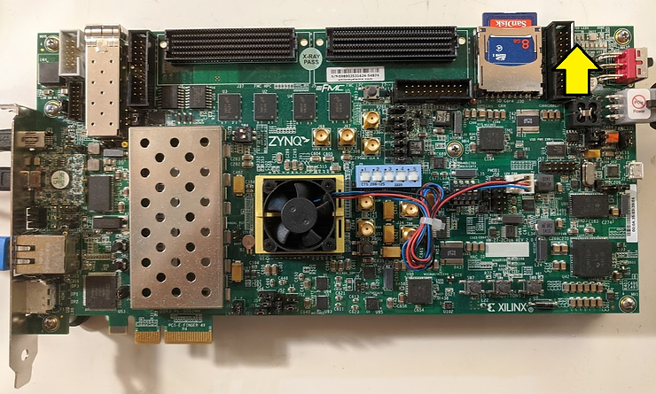
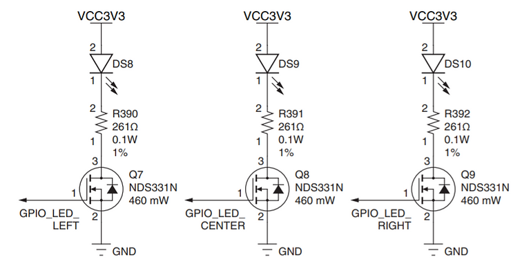
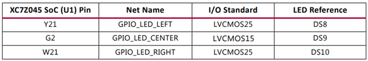
Note: This table is correct. Table 1-28 on page 60 of the ZC706 Evaluation Board User Guide UG954 (v1.8) August 6, 2019 is not correct (GPIO_LED_CENTER’s I/O Standard is not right)
Steps
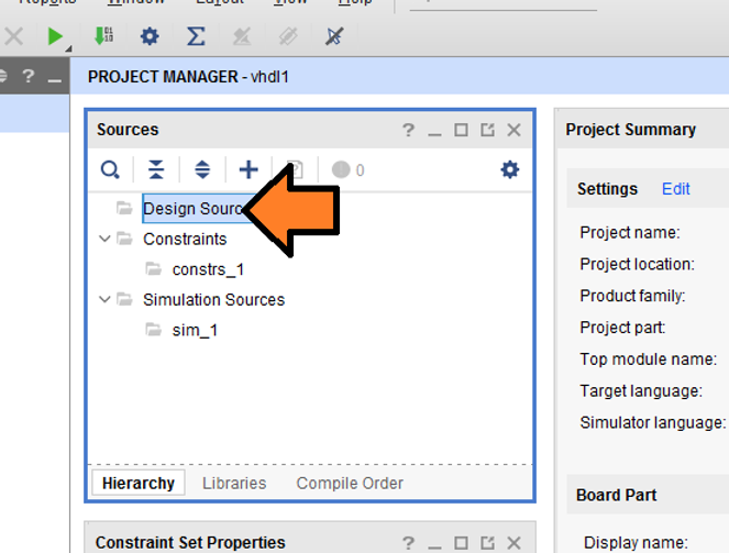
Step 1: Right-click Design Sources
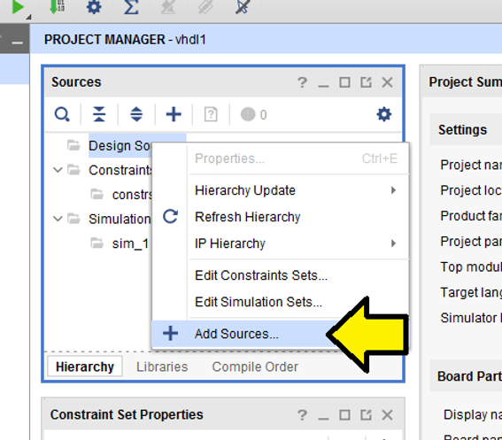
Step 2: Click Add Sources…
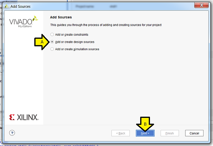
Step 3: (A) Click Add or create design sources and (B) click Next >
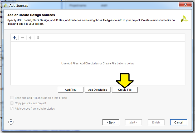
Step 4: Click Create File
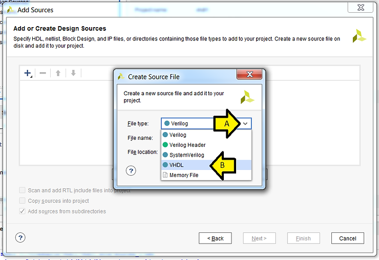
Step 5: (A) Click the down arrow and click (B) VHDL
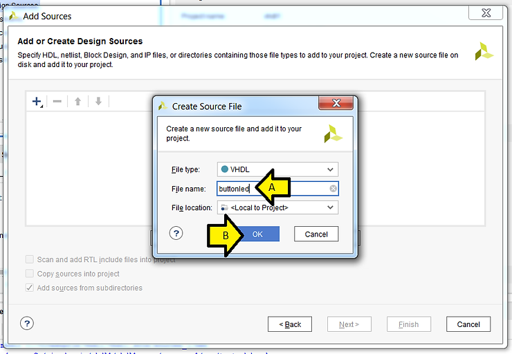
Step 6: (A) Enter buttoned as the File name: and (B) click OK
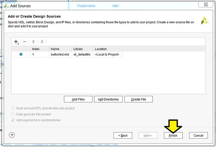
Step 7: Click Finish
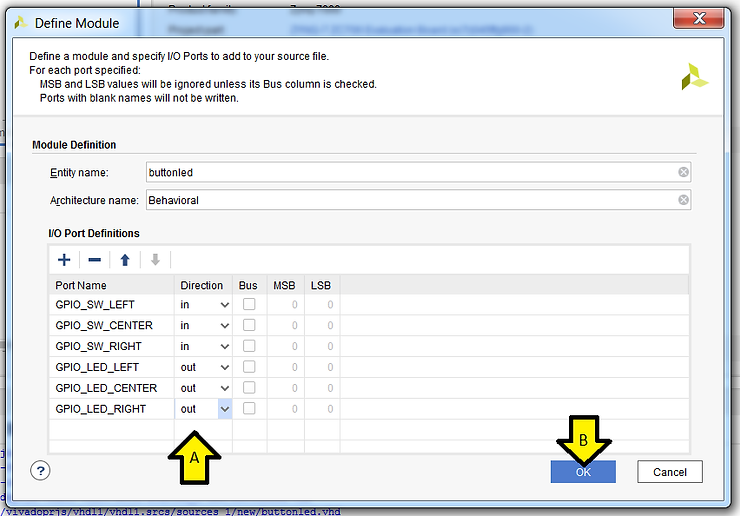
Step 8: Define the module
A)
Enter in:
GPIO_SW_LEFT
GPIO_SW_CENTER
GPIO_SW_RIGHT
…and
GPIO_LED_LEFT
GPIO_LED_CENTER
GPIO_LED_RIGHT
…and mark the Direction of the 3 GPIO_LED Port Names: out
B) Click OK
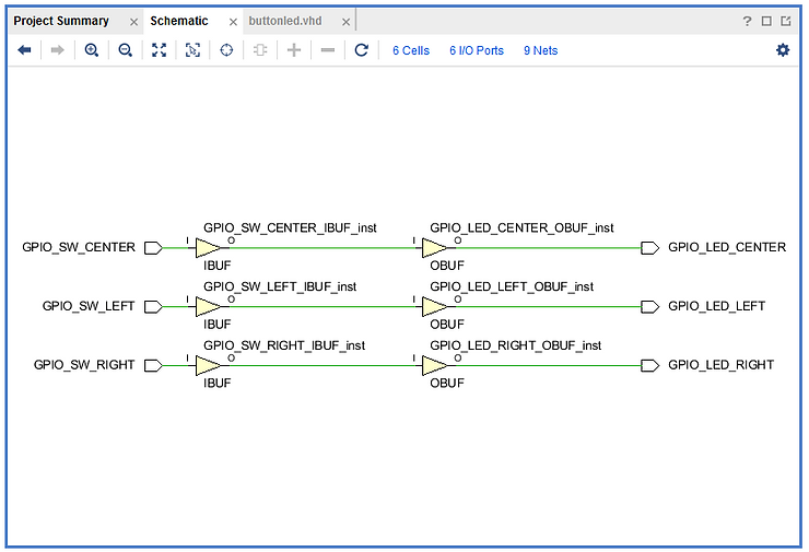
Step 9: Double click buttonled
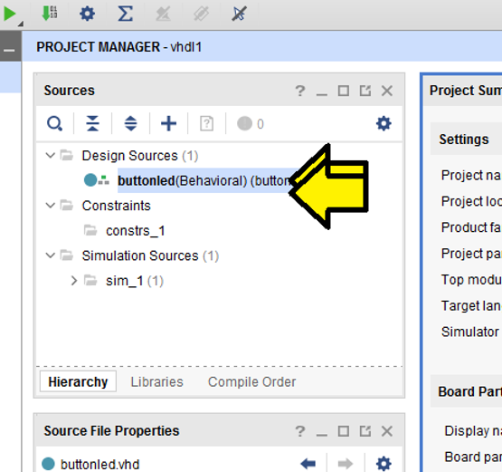
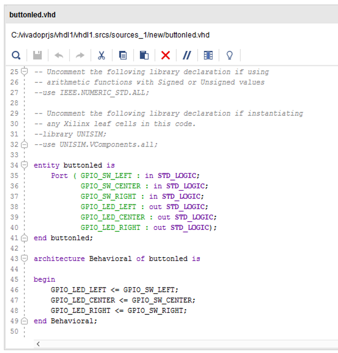
You should see:
Step 10:
Enter the following between begin and end Behavioral;
GPIO_LED_LEFT <= GPIO_SW_LEFT; GPIO_LED_CENTER <= GPIO_SW_CENTER; GPIO_LED_RIGHT <= GPIO_SW_RIGHT;
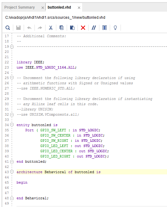
buttonled.vhd should look like this:
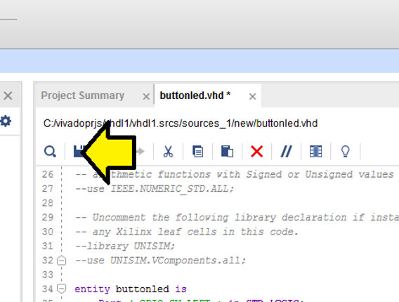
Step 11: Click save
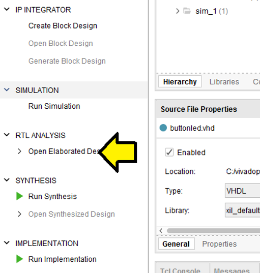
Step 12: Click Open Elaborated Design
Step 13: Click OK
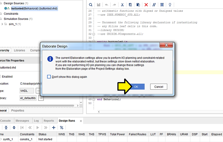
You should see pop-up status windows like:
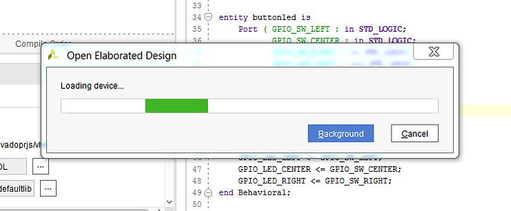
…and then:
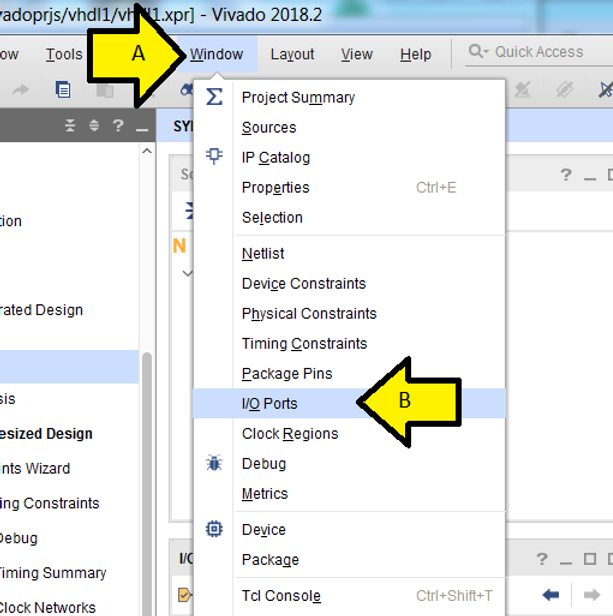
Step 14: (A) Click Window and (B) click I/O Ports
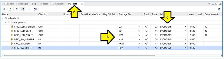
Step 15: (A) Click I/O Ports, (B) fill in the Package Pin as listed and (C) set in the I/O Std to LVCMOS15 for the CENTER ports and LVCMOS25 for the other ports (as shown above):
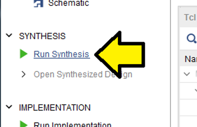
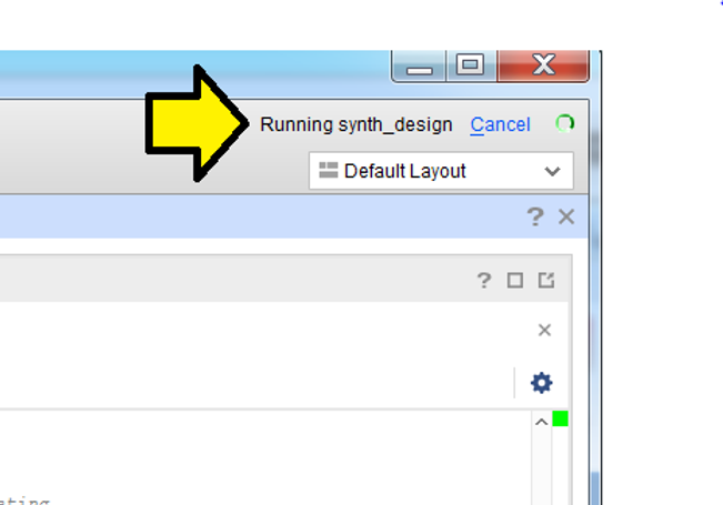
Step 16: Click Run Synthesis
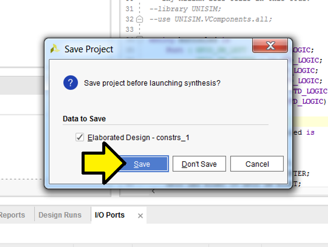
Step 17: Click Save
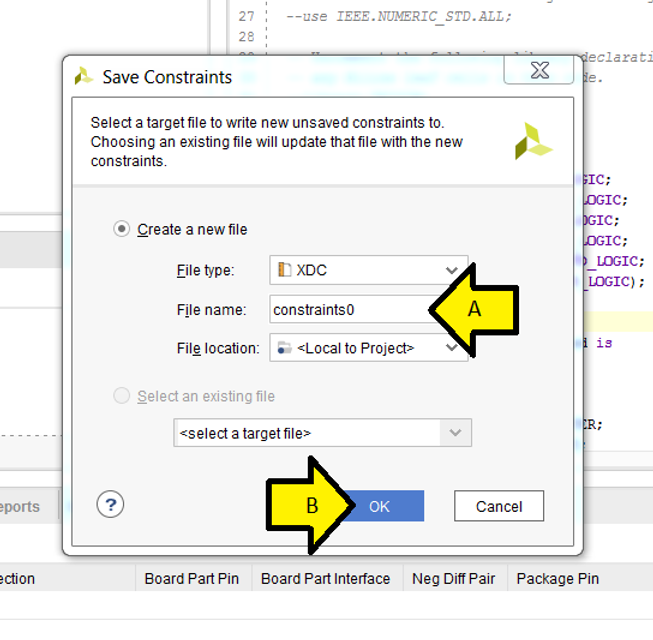
Step 18: (A) Set File name: to constraints0 and (B) click OK
Step 19: Accept the defaults and click OK
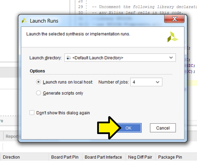
You should see some status in the upper right corner:
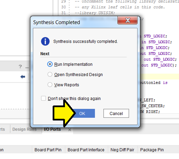
Step 20: Click OK to Run Implementation
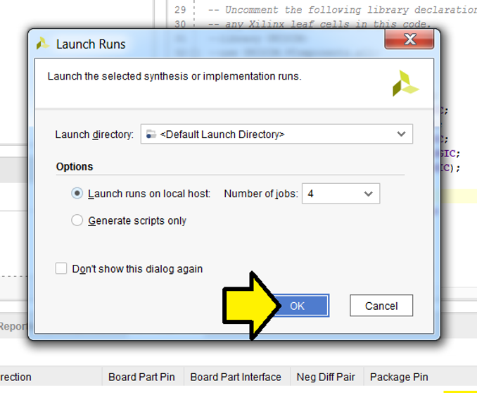
Step 21: Accept defaults and click OK
You should see the status of Implementation in the upper right corner:
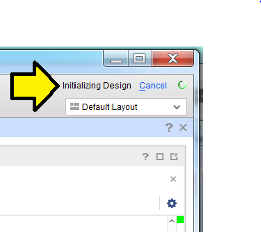
Note: implementation will take longer than synthesis
Step 22: (A) Select Generate Bitstream and (B) click OK
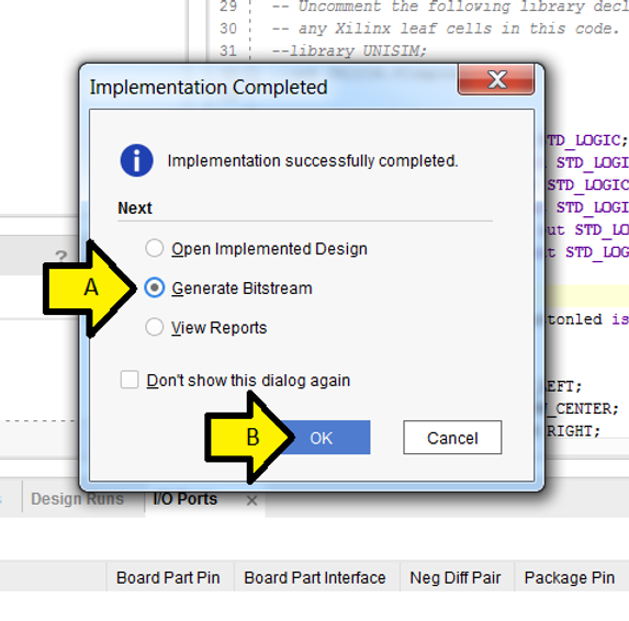
Step 23: Accept defaults and click OK
You will see the status of Generate Bitstream in the upper right corner
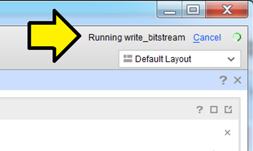
Note: This will take a little bit of time to complete (not as much as Implementation)
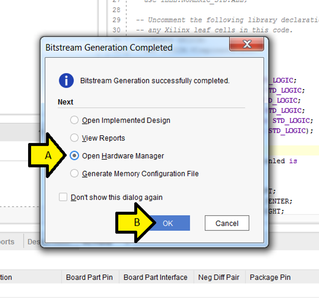
Step 24: (A) Click Open Hardware Manager and (B) click OK
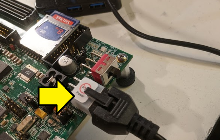
Step 25:
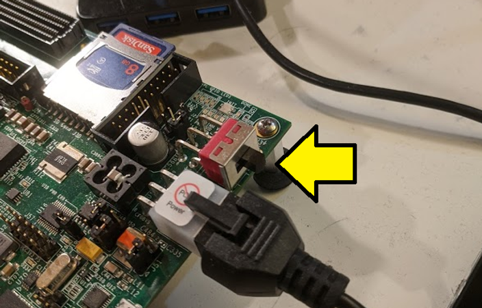
Plug the power supply into the board:
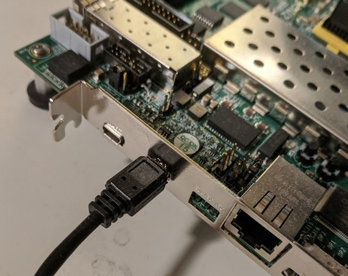
Plug the Micro-B end of a Micro-B to Standard-A USB cable into the Digilent USB-to-JTAG interface:
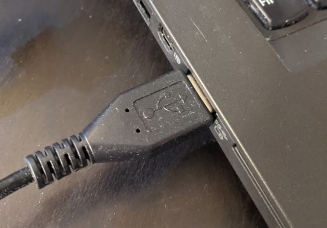
Plug the Standard-A end of a Micro-B to Standard-A USB cable into the computer
Power on the ZC706
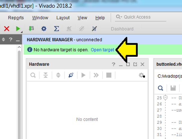
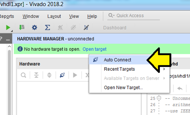
Step 26: Click Open target
Step 27: Click Auto Connect
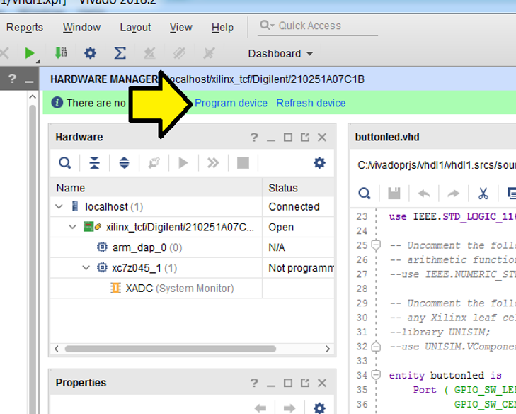
Step 28: Click Program device
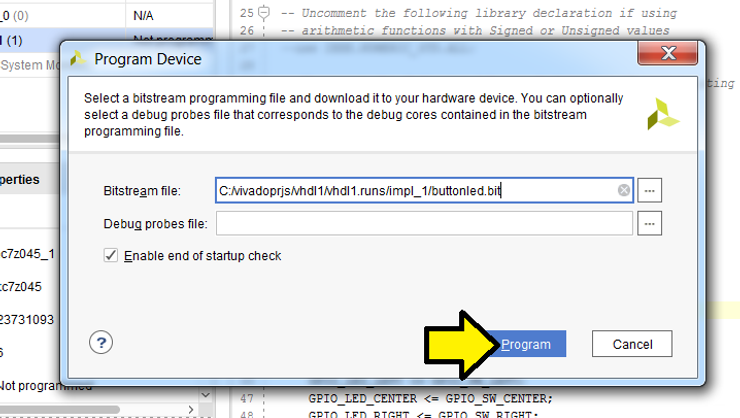
Step 29: Click Program
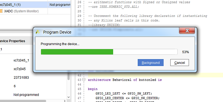
You should see:
Now when you press SW7, SW9 and SW 8, the PL LEDs will light up as seen here:
Extra
To see the constraints that get saved:
A) Click PROJECT MANAGEMENT
B) Expand Constraints (1)
C) Double click on constraints0.xdc (target)
D) Examine
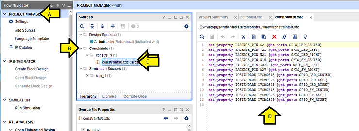
Here is the content of constraints0.xdc as text:
set_property PACKAGE_PIN G2 [get_ports GPIO_LED_CENTER] set_property PACKAGE_PIN Y21 [get_ports GPIO_LED_LEFT] set_property PACKAGE_PIN W21 [get_ports GPIO_LED_RIGHT] set_property PACKAGE_PIN K15 [get_ports GPIO_SW_CENTER] set_property PACKAGE_PIN AK25 [get_ports GPIO_SW_LEFT] set_property PACKAGE_PIN R27 [get_ports GPIO_SW_RIGHT] set_property IOSTANDARD LVCMOS15 [get_ports GPIO_LED_CENTER] set_property IOSTANDARD LVCMOS25 [get_ports GPIO_LED_LEFT] set_property IOSTANDARD LVCMOS25 [get_ports GPIO_LED_RIGHT] set_property IOSTANDARD LVCMOS15 [get_ports GPIO_SW_CENTER] set_property IOSTANDARD LVCMOS25 [get_ports GPIO_SW_LEFT] set_property IOSTANDARD LVCMOS25 [get_ports GPIO_SW_RIGHT]
References
-
Xilinx ZC706 User Guide [link] (no login required)
-
Xilinx ZC706 Schematics [link] (login required)
-
Xilinx logo from https://twitter.com/xilinxinc