Follow XD131 on 2025.1
This is a record of the steps I followed up to Step 10 of Programming an Embedded MicroBlaze Processor (XD131) using Vivado ML Enterprise 2025.1.
A PDF of the 2025.1 version can be found here.
Checked Vivado Version
I checked if Vivado ML Enterprise was needed to work with the SP701 FPGA Evaluation Kit. To figure this out I looked up the specific device on the board. The AMD Spartan 7 SP701 FPGA Evaluation Kit has an XC7S100 FPGA. According to Architecture Support this device is supported in the free Vivado Standard Edition.
Add 7 Series to Vivado
When creating a Vivado project for AMD Spartan 7 SP701 FPGA Evaluation Kit, I saw that I hadn’t installed 7 Series device support needed work with the XC7S100.
To add it I:
-
Launched the installer:
/home/demo/amd/v20251_2/.xinstall/2025.1/xsetup -
Selected Vivado ML Edition.
-
In the Vivado 2025.1 Installer – Select Extra Content window, enabled:
- [x] Devices
- [x] 7 Series
- [x] Spartan-7 FPGAs
- [x] 7 Series
- [x] Devices
-
Clicked Next through the remaining wizard screens, using defaults, to complete the installation.
After this, the 7 Series devices were available in my Vivado 2025.1 ML Edition install.
Follow Step 1
Started Step 1: Start the Vivado IDE and Create a Project.
Start Vivado
source /home/demo/amd/v20251_2/2025.1/Vivado/settings64.sh
mkdir -p ~/prjs/xd131
cd ~/prjs/xd131
vivado
Vivado launched with this output:
****** Vivado v2025.1 (64-bit)
  **** SW Build 6140274 on Wed May 21 22:58:25 MDT 2025
  **** IP Build 6138677 on Thu May 22 03:10:11 MDT 2025
  **** SharedData Build 6139179 on Tue May 20 17:58:58 MDT 2025
  **** Start of session at: Tue Sep  9 08:56:04 2025
    ** Copyright 1986-2022 Xilinx, Inc. All Rights Reserved.
    ** Copyright 2022-2025 Advanced Micro Devices, Inc. All Rights Reserved.

start_gui
Create a New Project
-
File → Project → New...
-
On Create a New Vivado Project, click Next.
-
On Project Name:
- Project name: mb0
- Project location:
/home/demo/prjs/xd131 - [✔] Create project subdirectory
- Click Next.
-
On Project Type:
- (●) RTL Project
- [✔] Do not specify sources at this time
- Click Next.
-
On Default Part:
- Select the Boards tab.
- Search for sp701.
- Choose Spartan-7 SP701 Evaluation Platform.
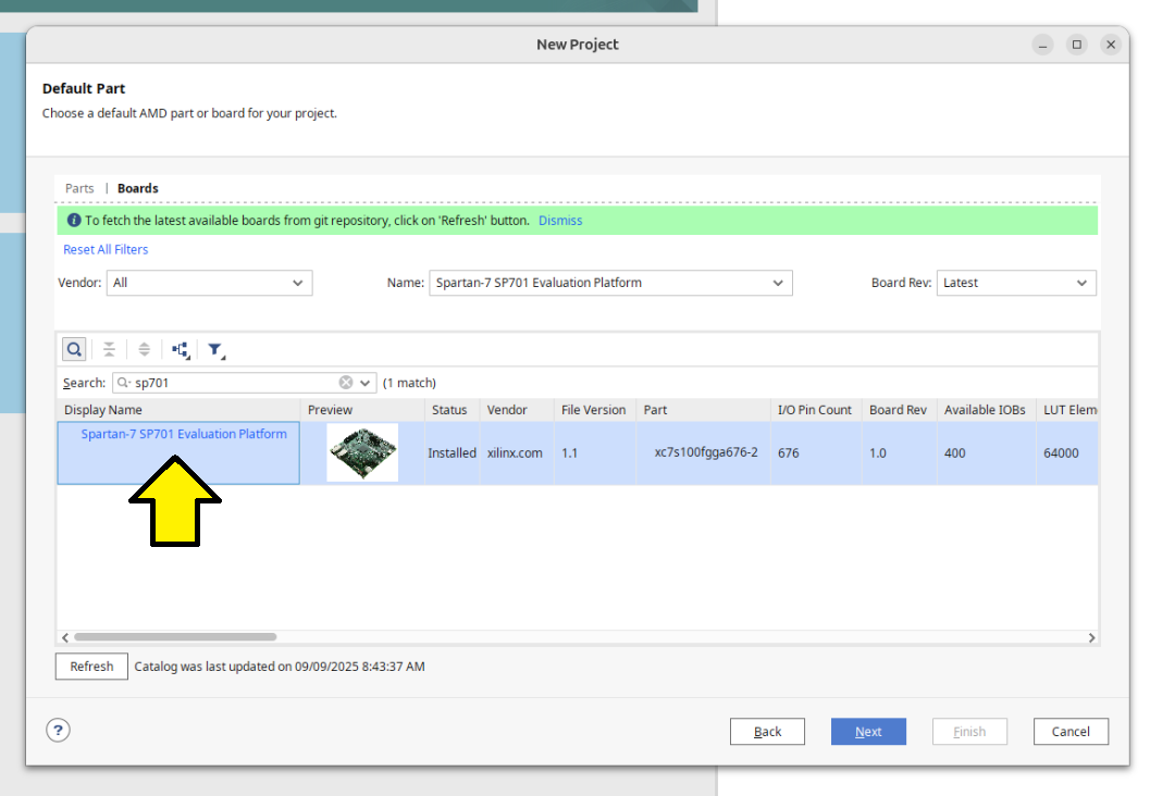
[!CAUTION]
If you don’t see Spartan-7 Evaluation Platform listed, install support for Devices > 7 Series > Spartan-7 FPGAs during your Vivado installation. See the instructions above to add support for this device to your current installation.
[!NOTE]
The Name: Spart-7 SP701 Evaluation Platform existed even though I didn’t have Devices > 7 Series > Spartan-7 FPGAs installed. This looks like a bug.
- Clicked Next to progress to the New Project: New Project Summary screen:
( ! ) A new RTL project named mb0 will be created
( ! ) The default part and product family for the new project: Default Board: Spartan-7 SP701 Evaluation Platform Default Part: xc7s100fpga676-2 Family: Spartan-7 Package: fpga676 Speed Grade:-2
- On the New Project: New Project Summary screen, clicked Finish.
Follow Step 2
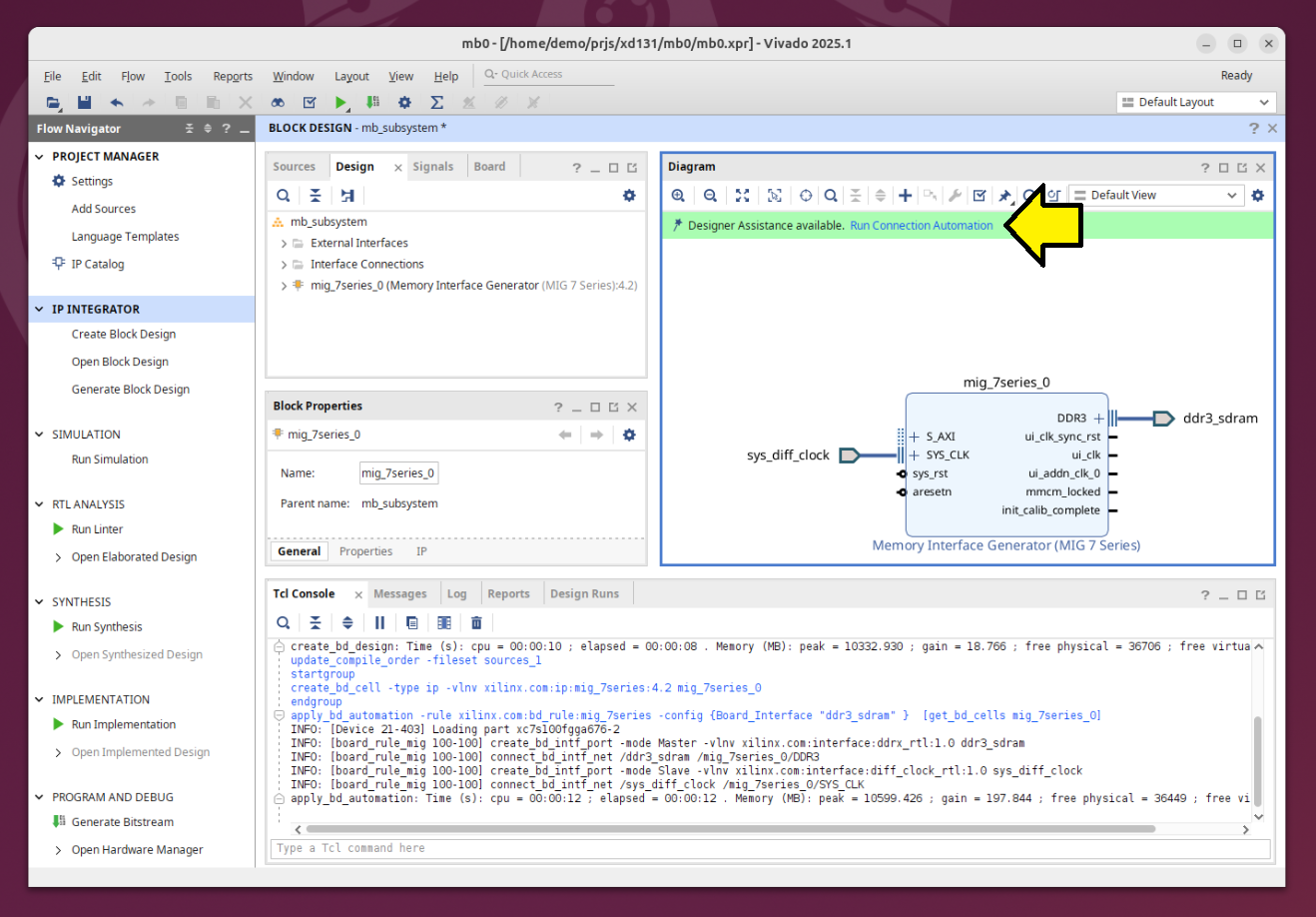
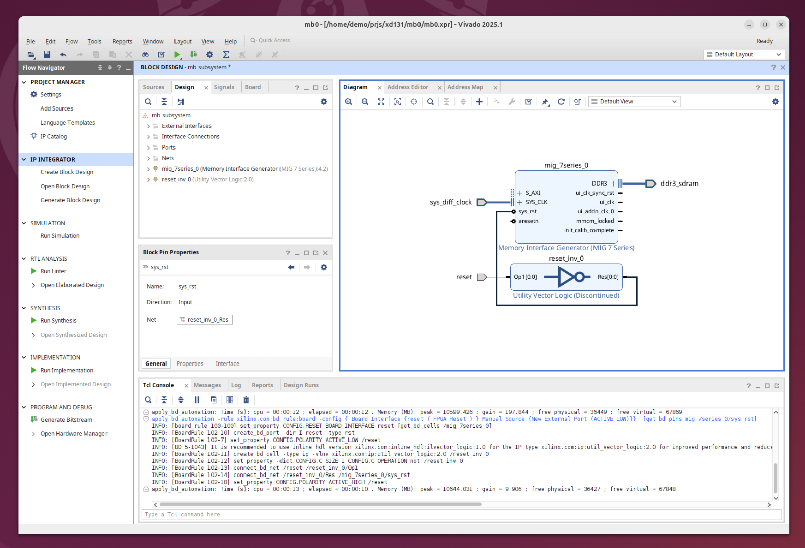
I followed Step 2: Create an IP Integrator Design until I completed the 7th step of Step 2.
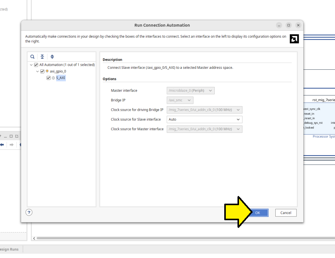
After the 7th step, I clicked Run Connection Automation:
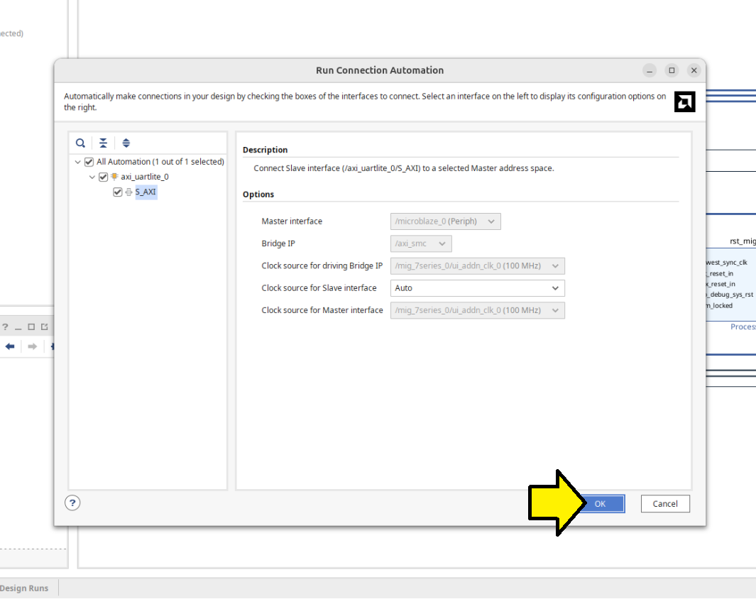
Used the Run Connection Automation screen defaults and clicked OK:
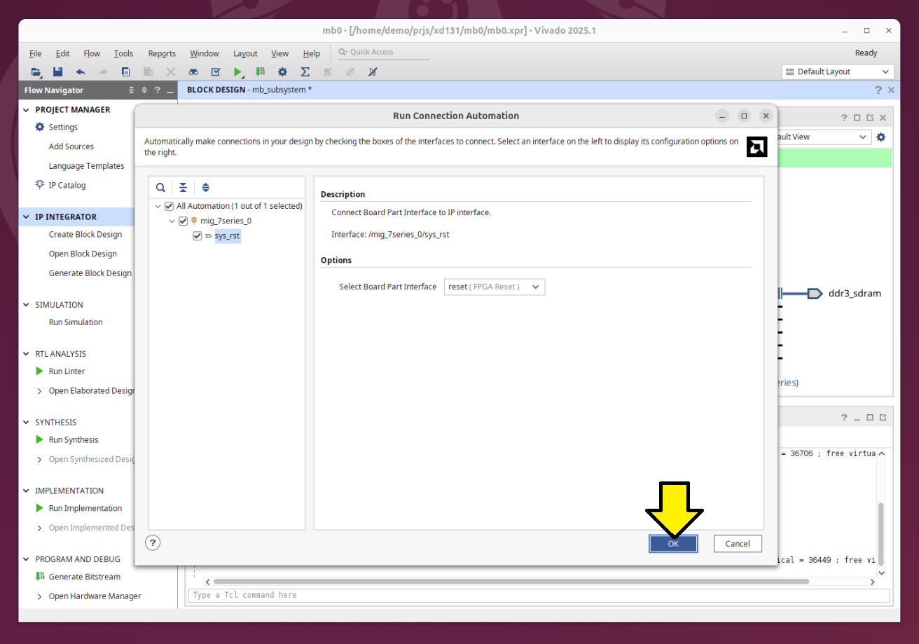
Saw:
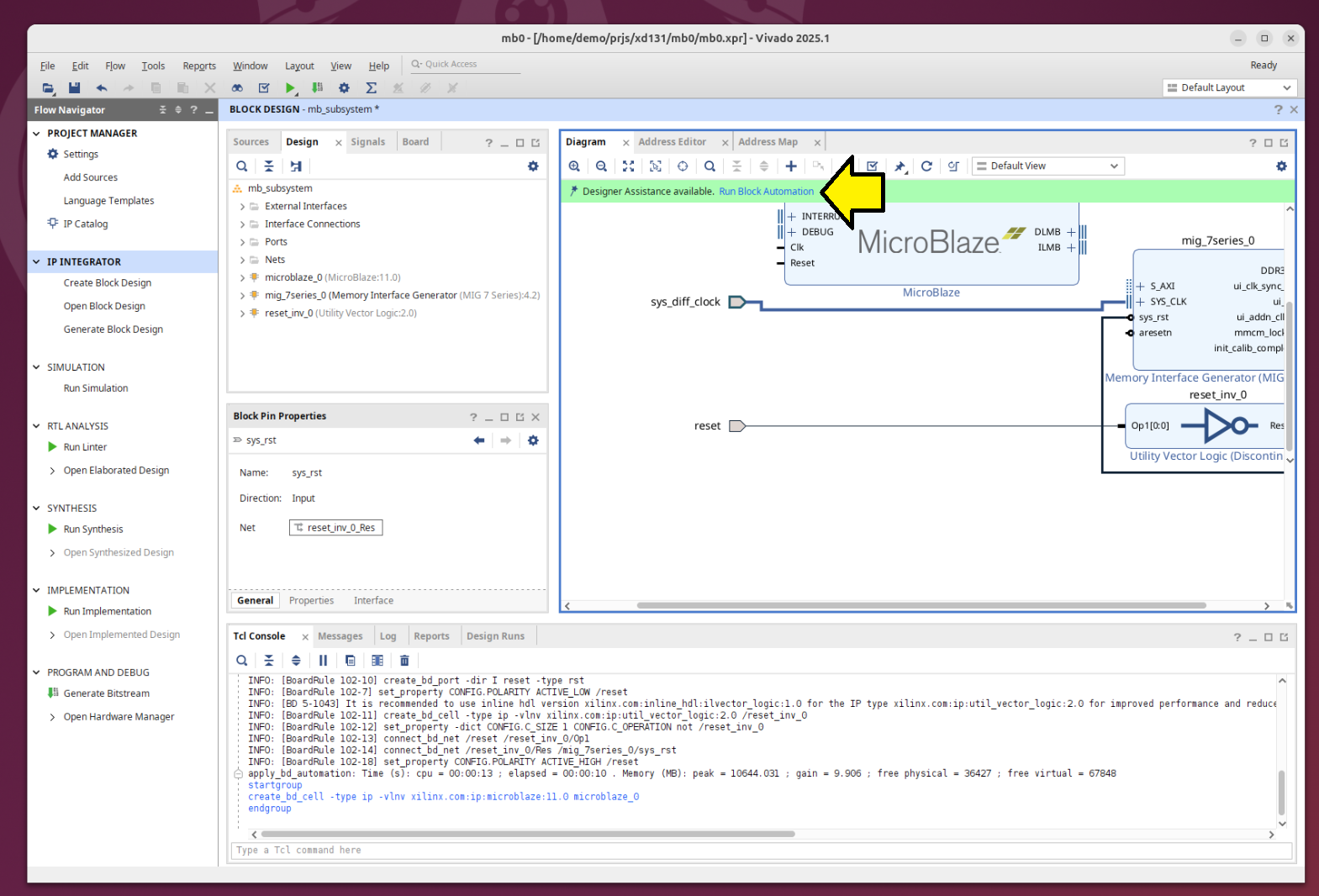
Continued Step 2, parts 8 and 9. After step 9, clicked Run Block Automation again and followed these steps instead of those listed:
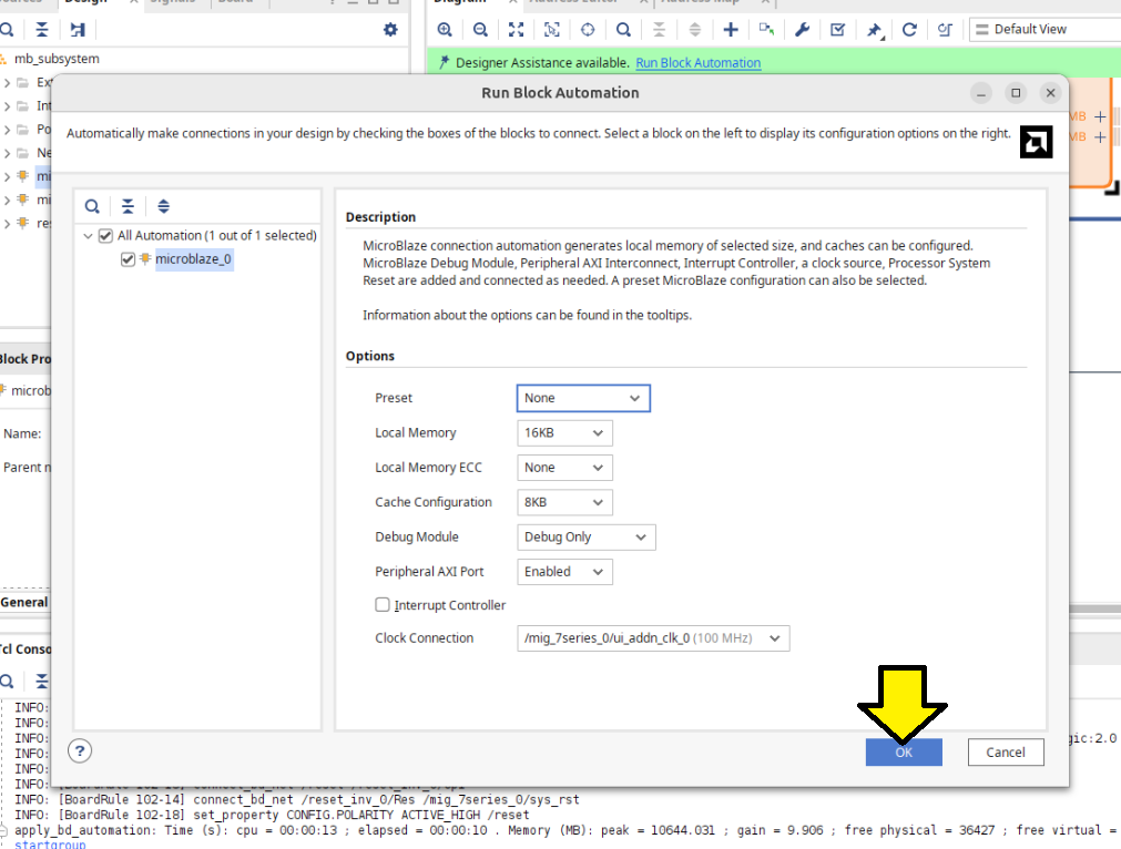
Accepted the defaults on the Run Block Automation screen and clicked OK:
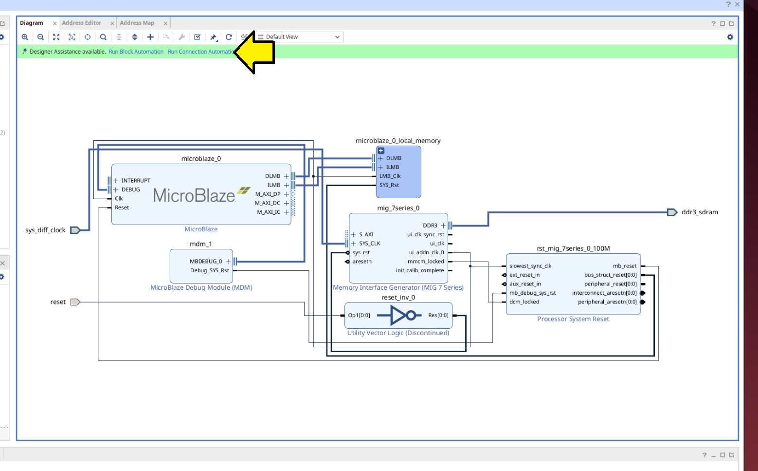
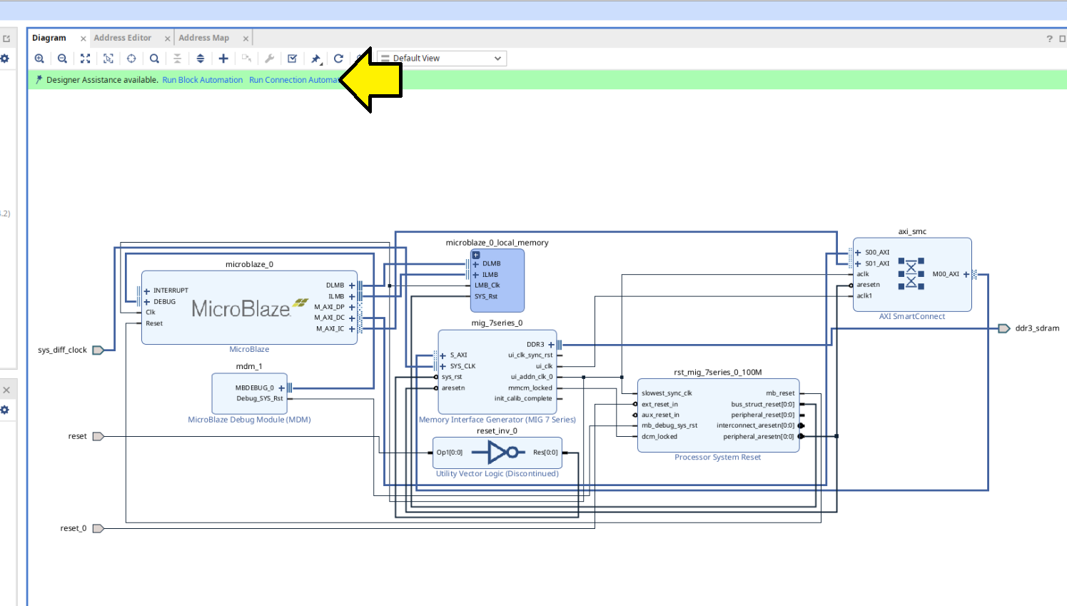
Clicked Run Connection Automation when I saw:
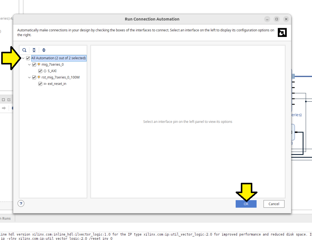
Made sure to select All Automation and click OK:
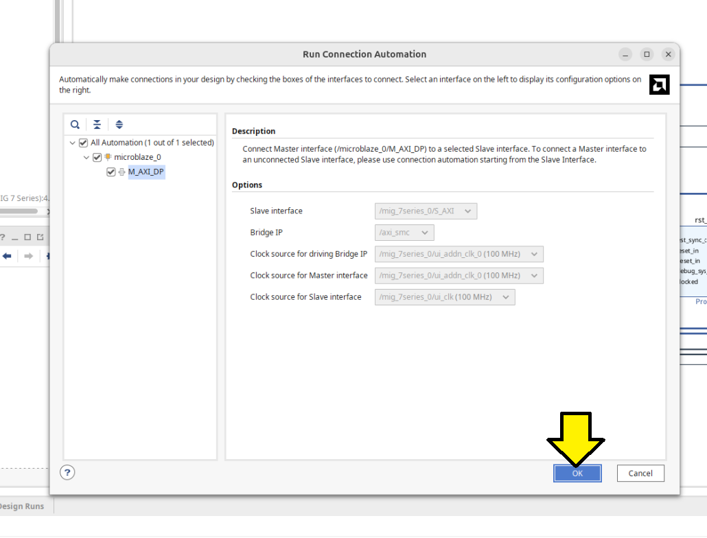
On the next screen click Run Connection Automation again:
Accept defaults and click OK on the Run Connection Automation screen that pops up:
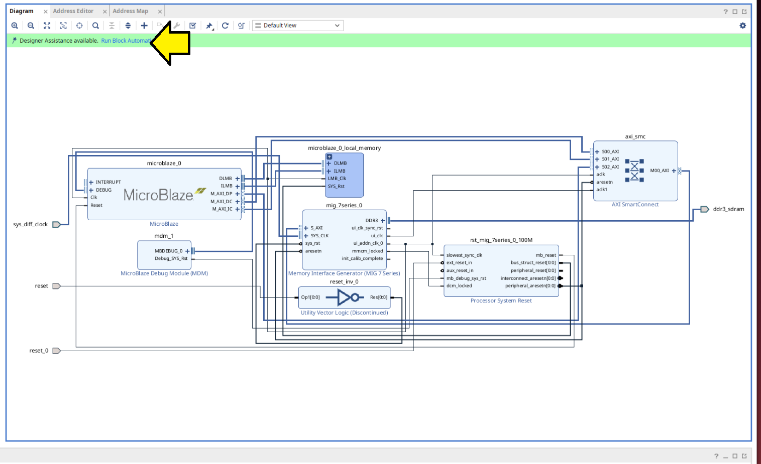
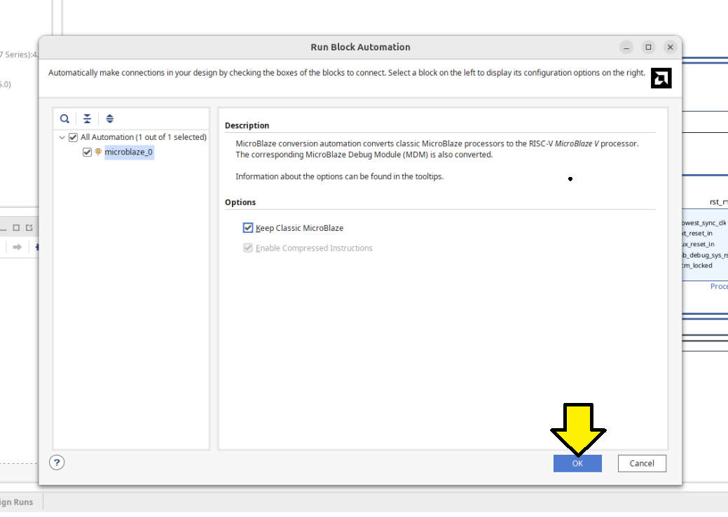
Now click Run Block Automation:
Accept the defaults and click OK:
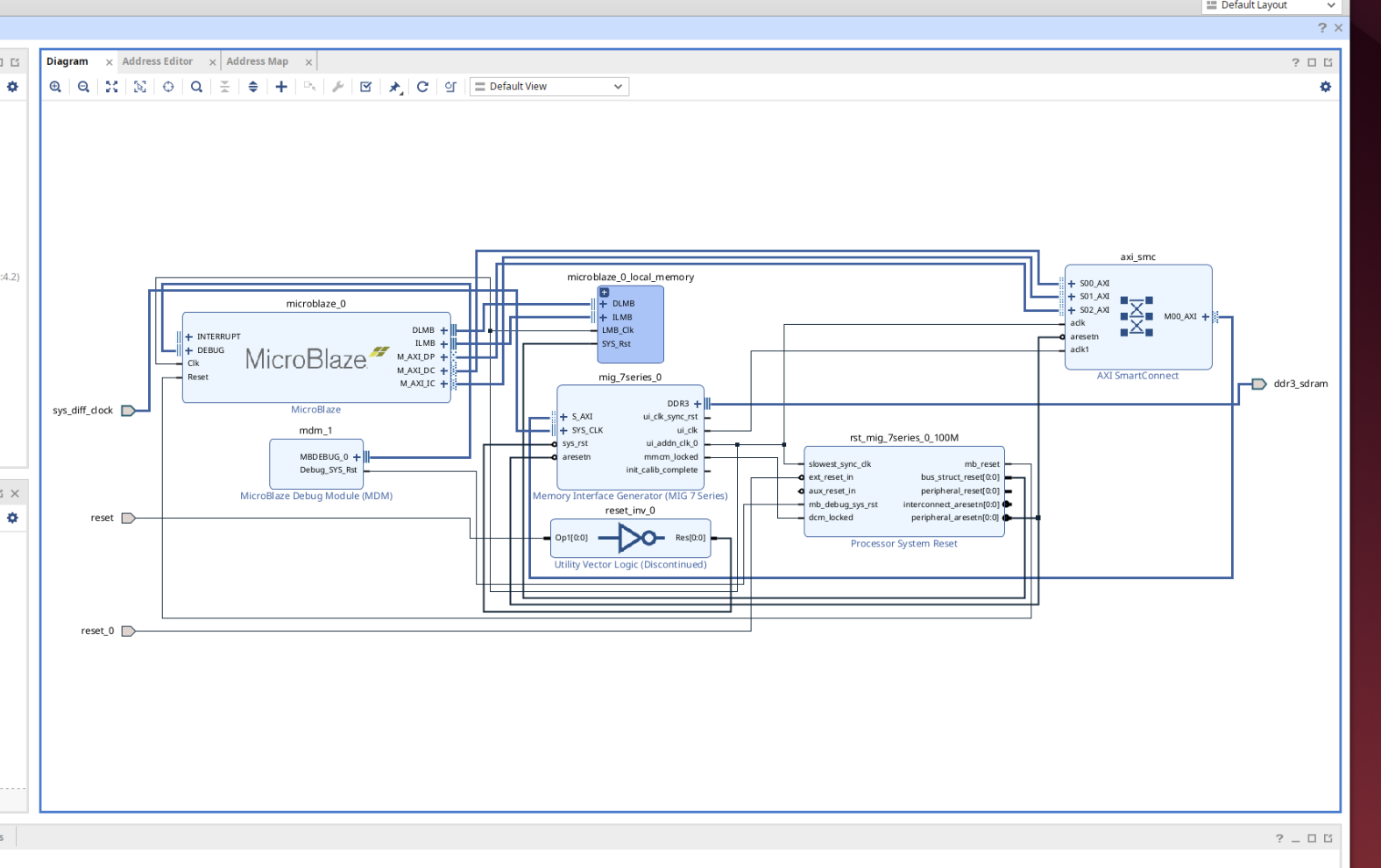
You should see something like this:
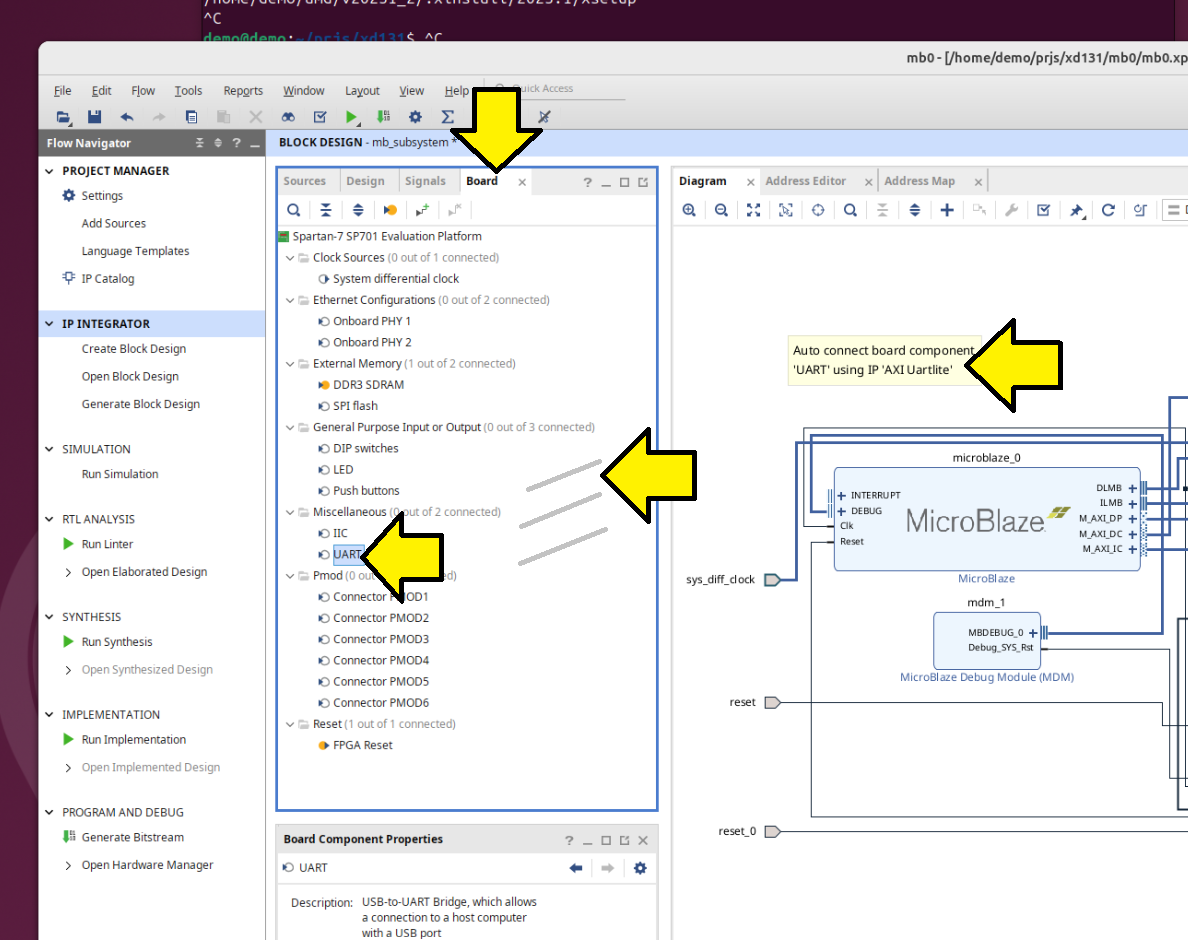
Click Board tab, click and drag UART onto the diagram:
Click OK and click Run Connection Automation:
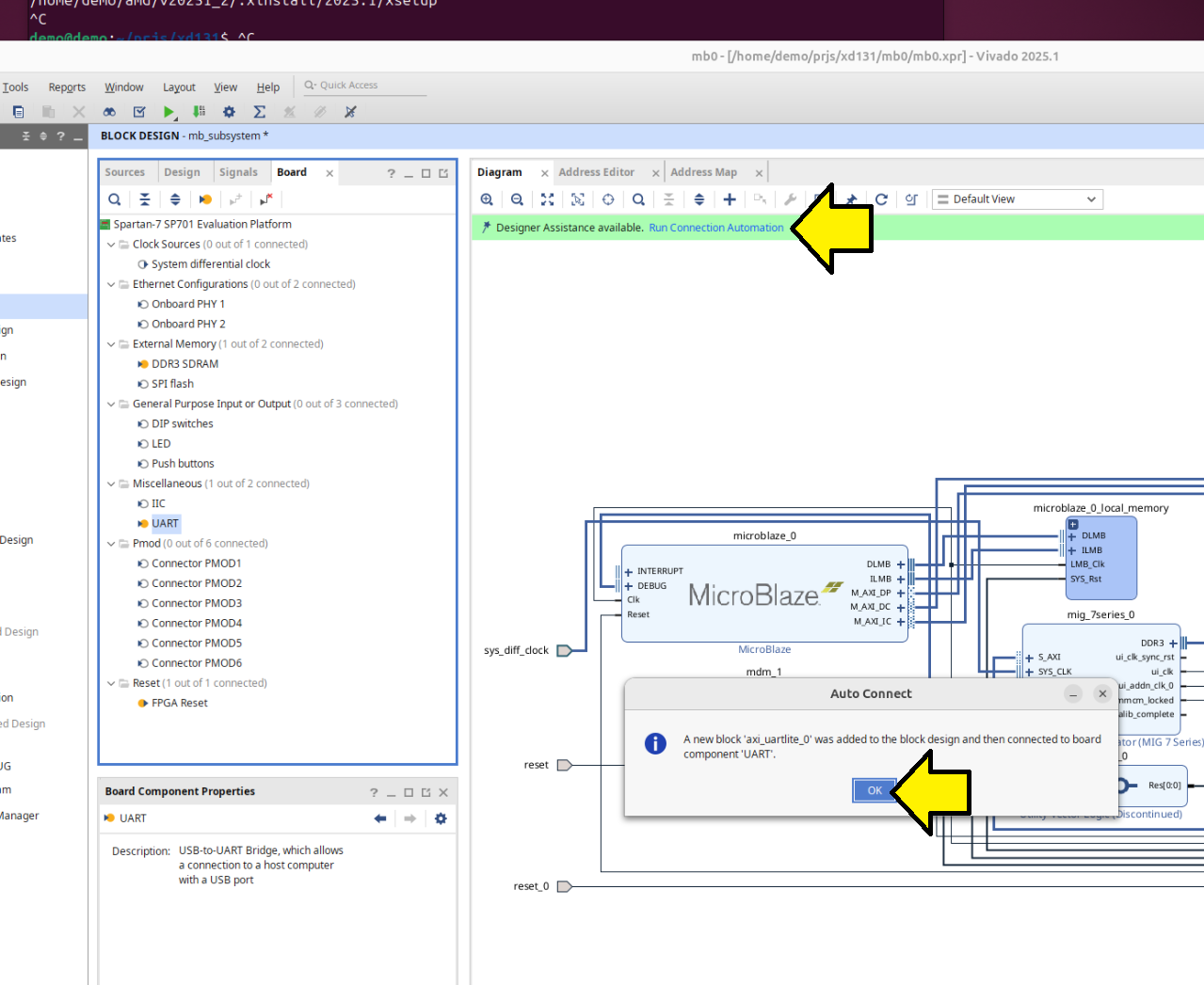
Accept defaults (axi_uartlite_0 selected) and click OK:
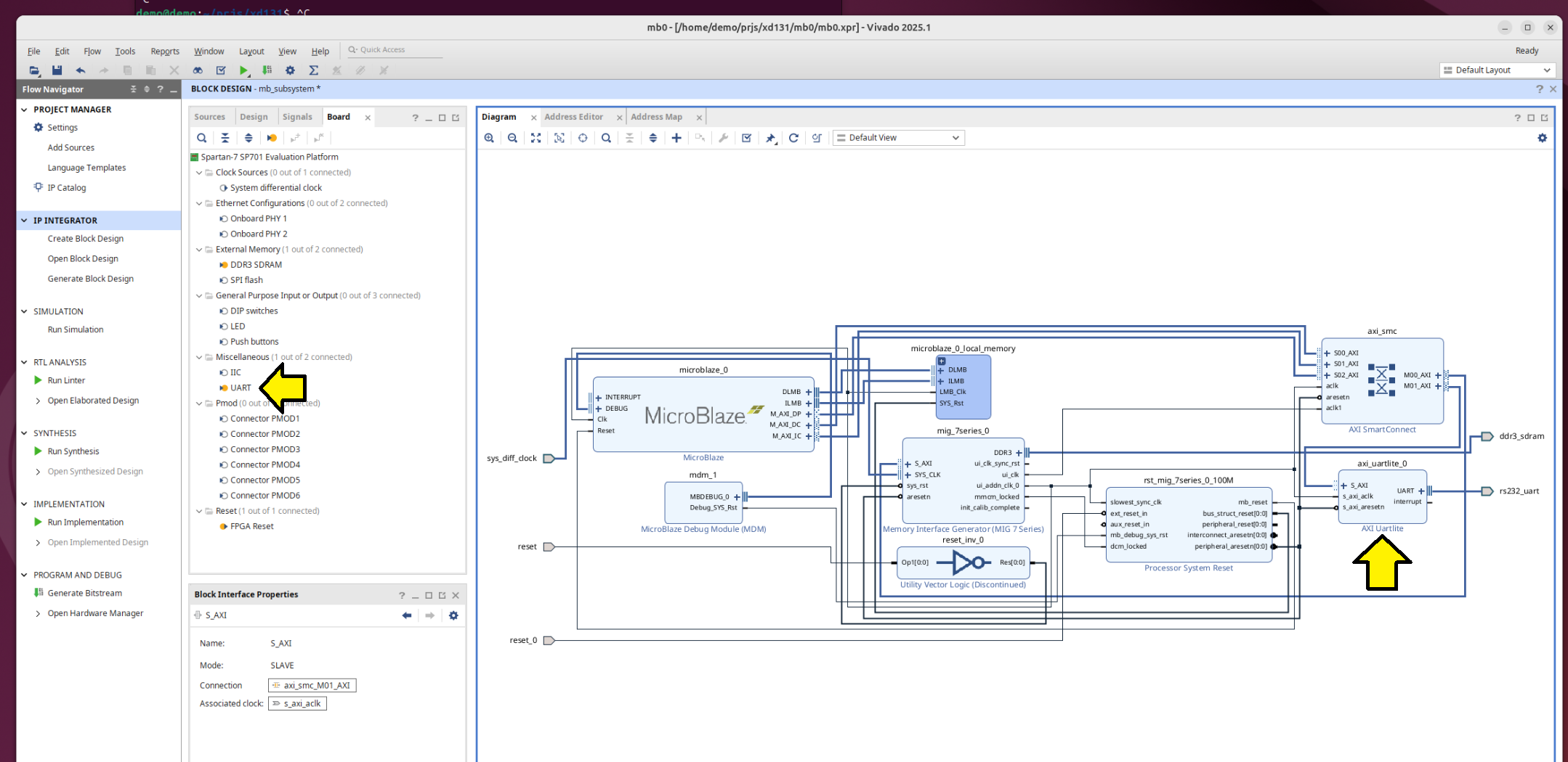
Saw a axi_uartlite_0 in the block design:
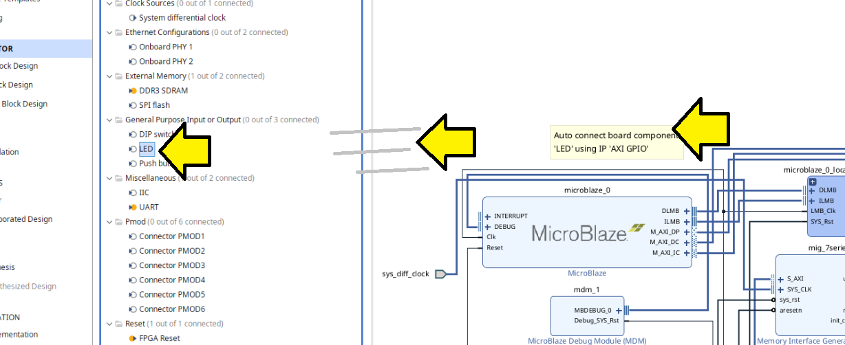
To keep aligned with the original guide, pulled the LED in:
Again, clicked OK and clicked Run Connection Automation:
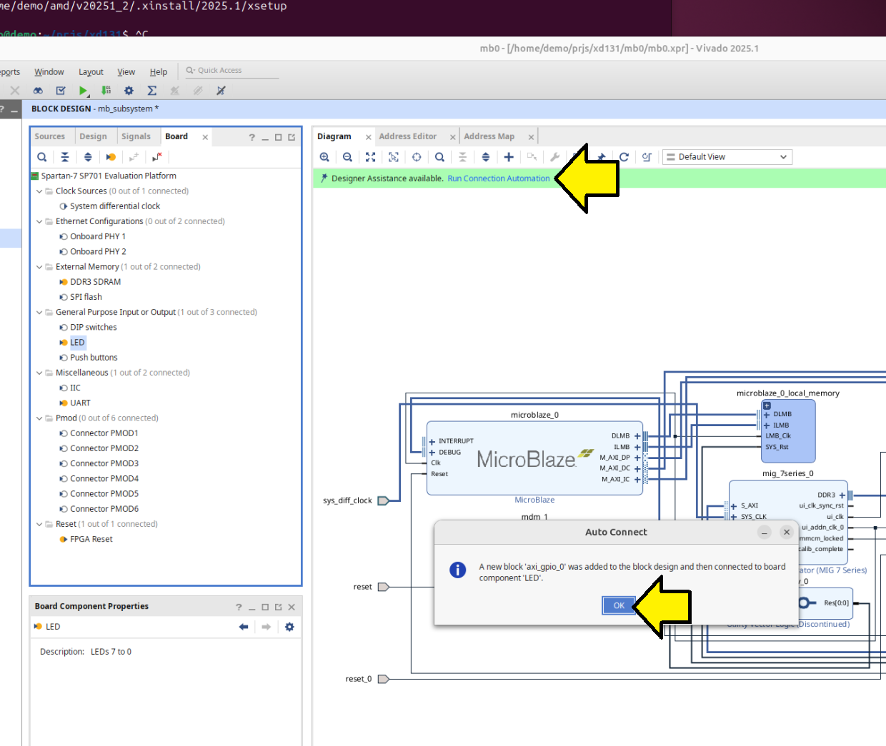
Clicked OK to run automation:
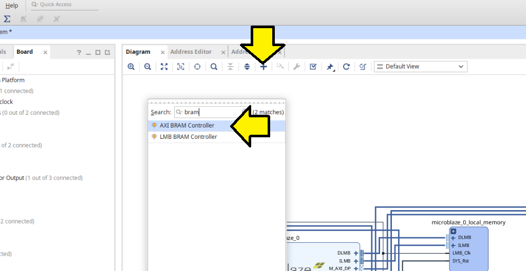
Added the AXI BRAM controller:
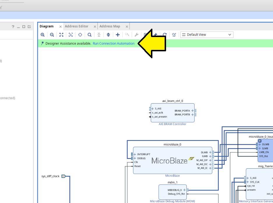
Clicked Run Connection Automation:
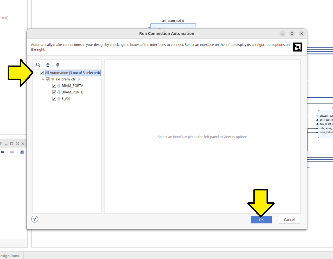
Selected All Automation (3 out of 3 selected) and clicked OK:
My block design looked like this:
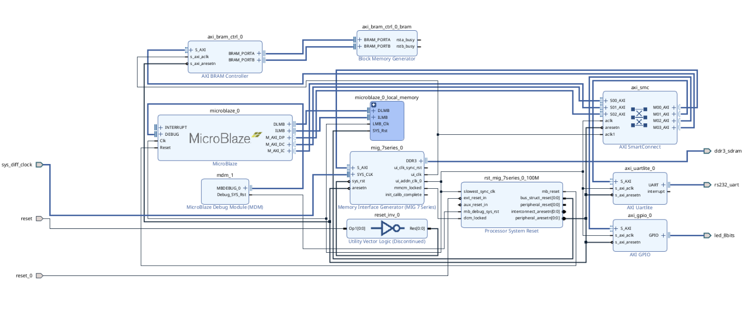
[!WARNING]
Later, I saw an implementation error because I had reset and reset_0. I fixed this later by removing reset_0 and connecting rst_mig_7series_0_100M to reset.
Now marked nets for debugging. Right-clicked on the axi_gpio_0’s S_AXI port and selected Debug.
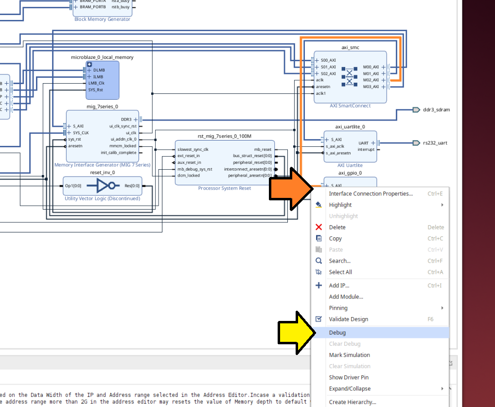
[!IMPORTANT]
The guide said I should right-click on M00_AXI, but depending on automation, axi_gpio_0 may be on a different M0*_AXI interface.
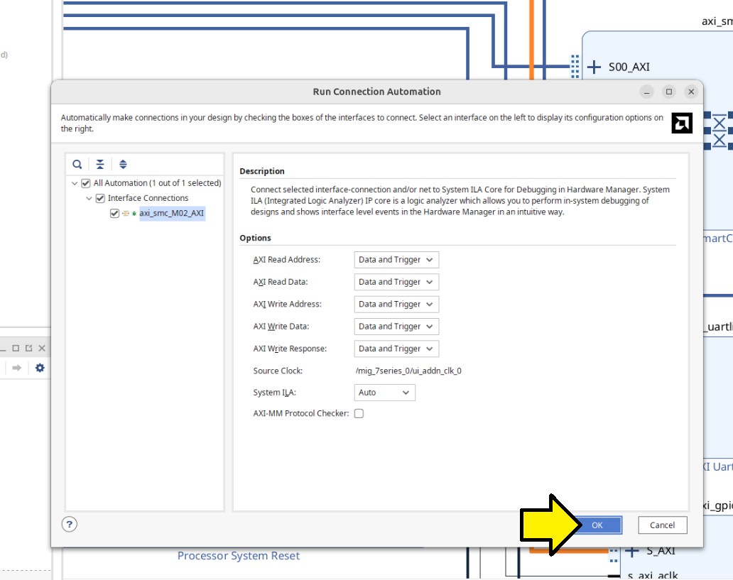
Checked that I saw little green bugs by the ports and clicked Run Connection Automation:
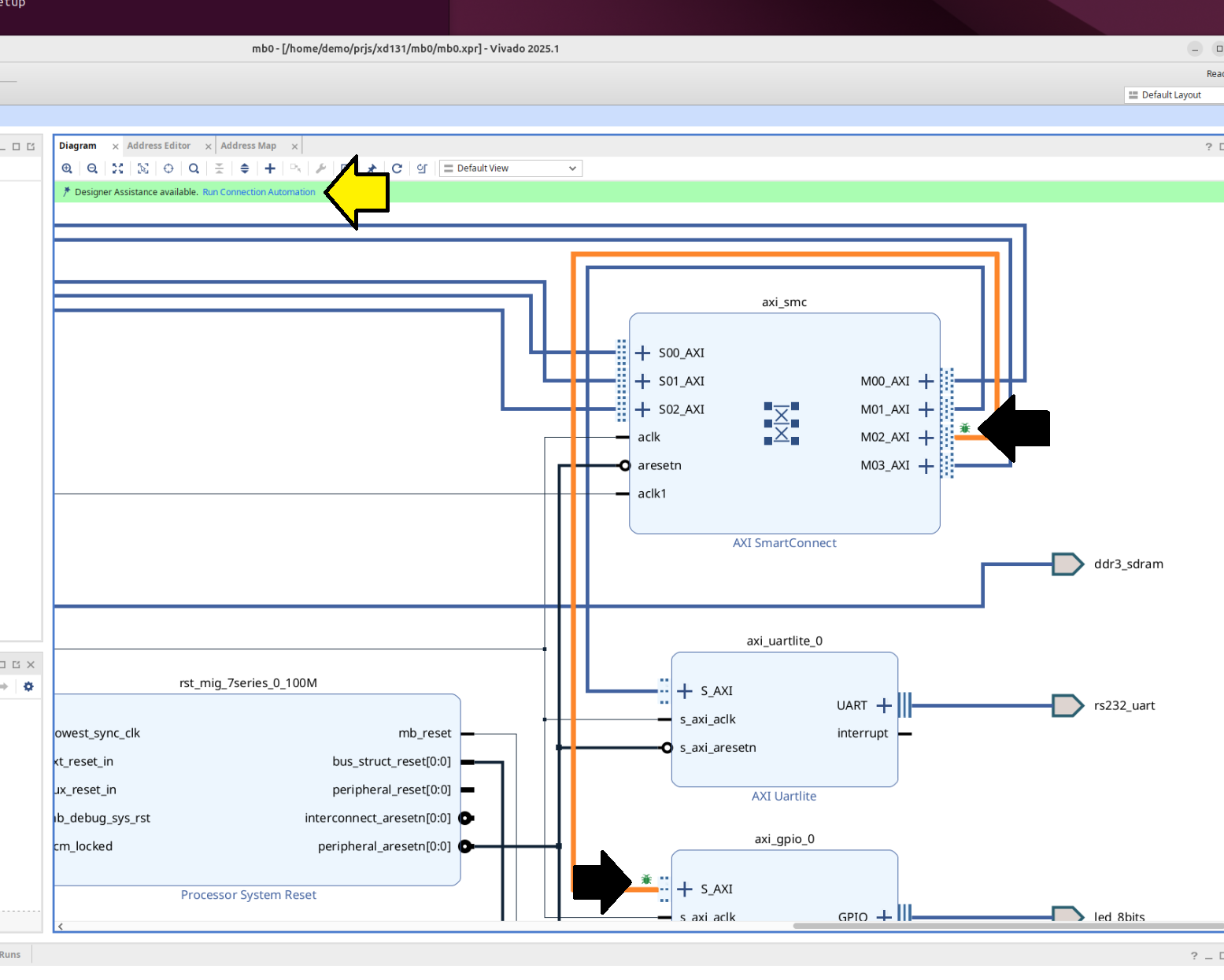
Clicked OK to run the automation:
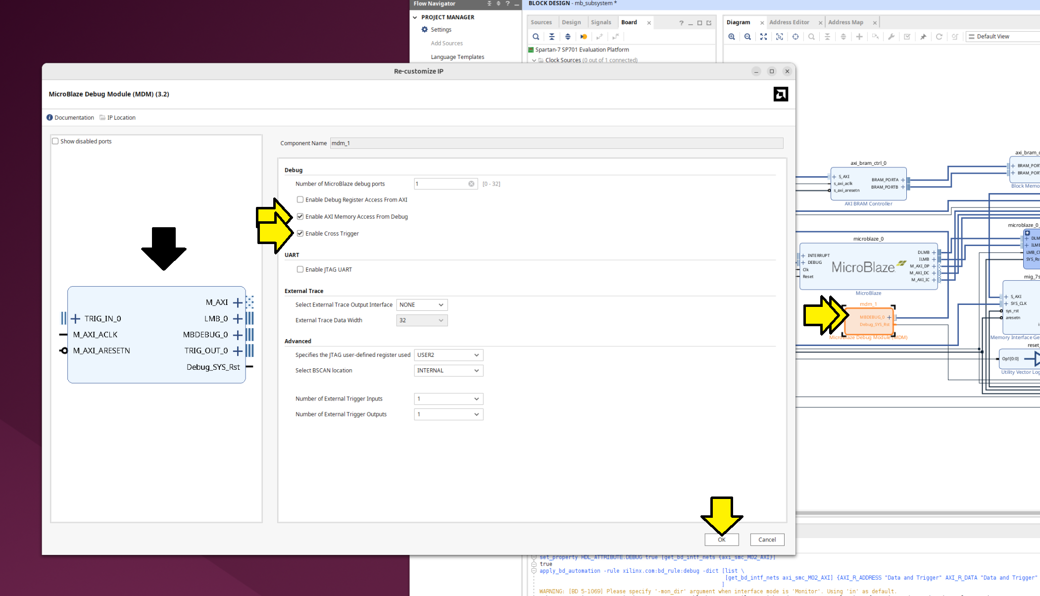
Double clicked mdm_0 and selected:
[ x ] Enable AXI Memory Access From Debug
[ x ] Enable Cross Trigger.
Noticed that the block diagram changed. Left all other options at their default and clicked OK.
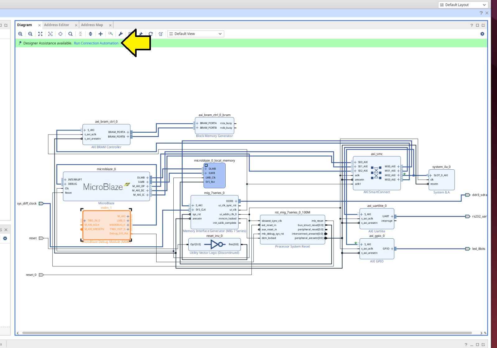
Clicked Run Connection Automation:
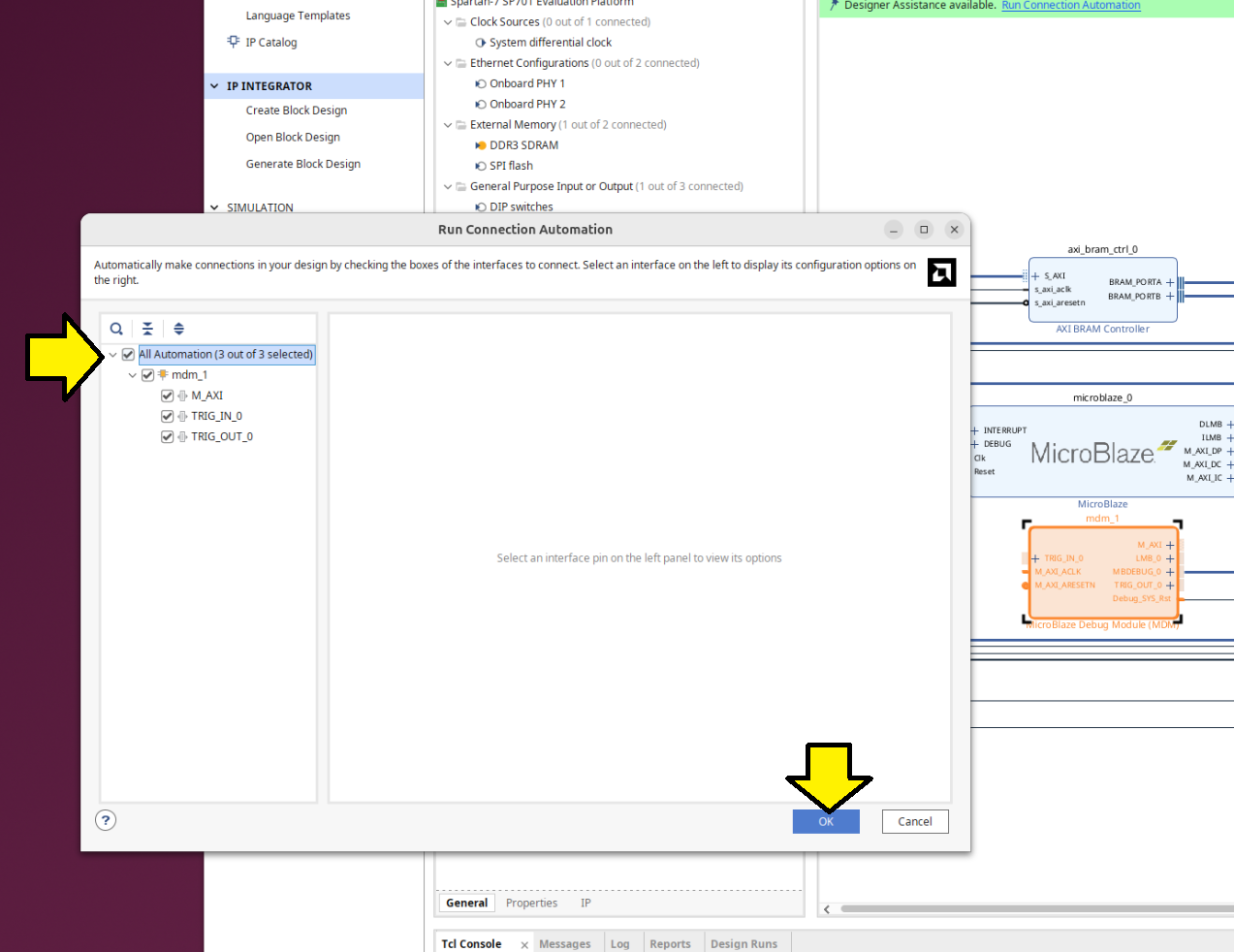
Selected All automation (3 out of 3 selected) and clicked OK:
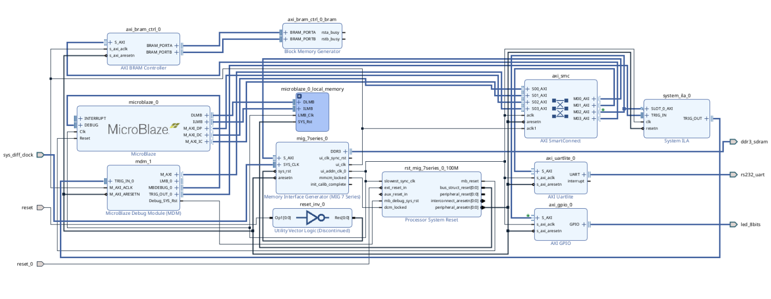
The full diagram now contained all of the components listed in the original guide:
Follow Step 3
Skipped checking the address ranges because it will be caught later if there’s an issue.
Follow Step 4
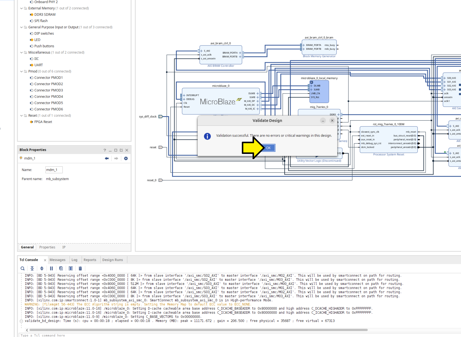
Continued with Step 4: Validate Block Design. Saw Validation successful.:
Follow Step 5
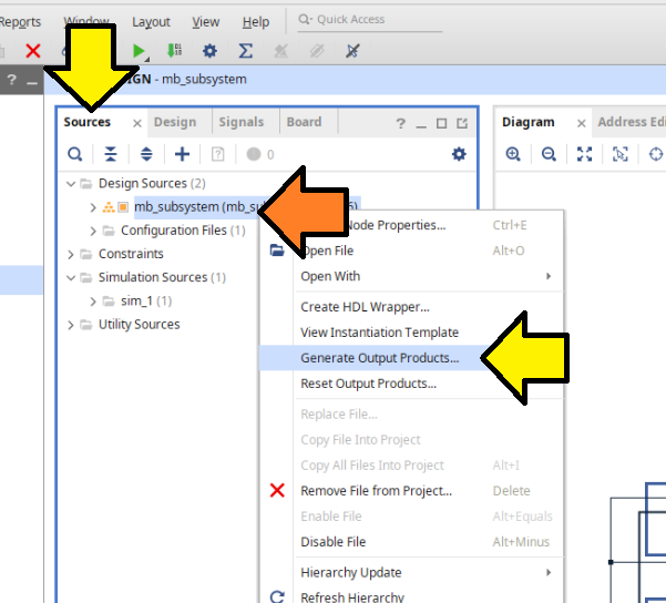
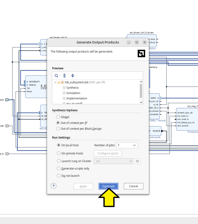
Continued with Step 5, which toke some 90-ish min on my 8 core 17.5.2 VMWare Workstation VM with 64 GB or RAM). Here’s a diagram missing from the guide on where to click Generate Output Products.
Clicked Generate:
[!NOTE]
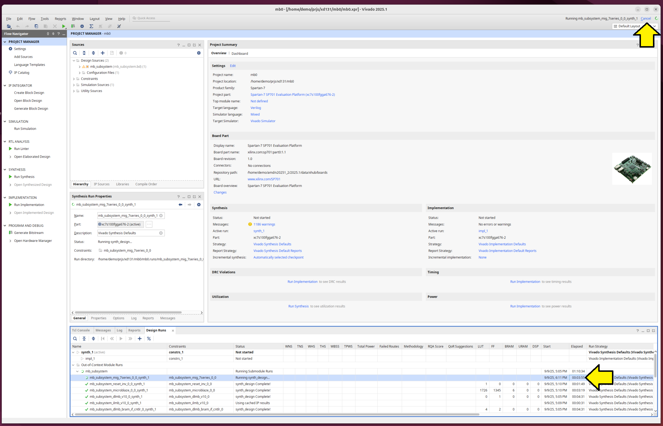
The first time I ran Generate Output Products, I launched it and then switched from the Linux VM desktop to another Windows 11 desktop. When I returned to the VM, the UI was frozen with a small red icon with an in the top right of my Ubuntu 24.04.3 desktop, and the Vivado GUI was unresponsive. Clicking the icon made it disappear.
I killed Vivado and restarted it. When I restarted Vivado, the GUI was responsive, and I saw the Running mb_subsystem_mig_7serier_0_0_synth_1 status in the top right of the Vivado GUI. However, after 30 minutes and not seeing Elapsed update, I canceled the run and restarted Generate Output Products. It finished. I noticed the UI was stuck again. I killed Vivado and restarted.
It seem that when I saw
'this->recurse > 0' failed at ../src/pipewire/thread-loop.c:63 do_unlock()demo@demo:~/prjs/xd131$ vivado ****** Vivado v2025.1 (64-bit) **** SW Build 6140274 on Wed May 21 22:58:25 MDT 2025 **** IP Build 6138677 on Thu May 22 03:10:11 MDT 2025 **** SharedData Build 6139179 on Tue May 20 17:58:58 MDT 2025 **** Start of session at: Tue Sep 9 17:18:54 2025 ** Copyright 1986-2022 Xilinx, Inc. All Rights Reserved. ** Copyright 2022-2025 Advanced Micro Devices, Inc. All Rights Reserved. start_gui 'this->recurse > 0' failed at ../src/pipewire/thread-loop.c:63 do_unlock()…the UI had hung.
Follow Step 6
Continued with Step 6: Create a Top-Level Wrapper. No issues.
Follow Step 7
Continued with Step 7: Take the Design through Implementation.
I saw a warning and an error:
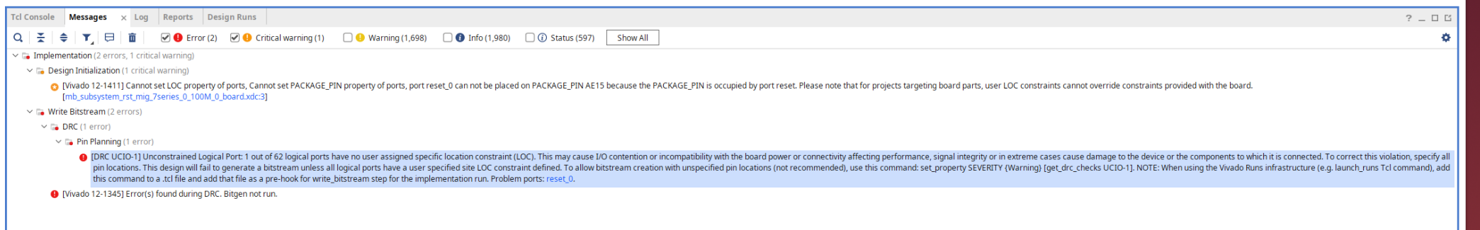
In text:
Implementation > Design Initialization
[Vivado 12-1411] Cannot set LOC property of ports, Cannot set PACKAGE_PIN property of ports, port reset_0 can not be placed on PACKAGE_PIN AE15 because the PACKAGE_PIN is occupied by port reset. Please note that for projects targeting board parts, user LOC constraints cannot override constraints provided with the board. ["/home/demo/prjs/xd131/mb0/mb0.gen/sources_1/bd/mb_subsystem/ip/mb_subsystem_rst_mig_7series_0_100M_0/mb_subsystem_rst_mig_7series_0_100M_0_board.xdc":3]
Write Bitstream > DRC > Pin Planning
demo@demo:~/Desktop$ # [DRC UCIO-1] Unconstrained Logical Port: 1 out of 62 logical ports have no user assigned specific location constraint (LOC). This may cause I/O contention or incompatibility with the board power or connectivity affecting performance, signal integrity or in extreme cases cause damage to the device or the components to which it is connected. To correct this violation, specify all pin locations. This design will fail to generate a bitstream unless all logical ports have a user specified site LOC constraint defined. To allow bitstream creation with unspecified pin locations (not recommended), use this command: set_property SEVERITY {Warning} [get_drc_checks UCIO-1]. NOTE: When using the Vivado Runs infrastructure (e.g. launch_runs Tcl command), add this command to a .tcl file and add that file as a pre-hook for write_bitstream step for the implementation run. Problem ports: reset_0.
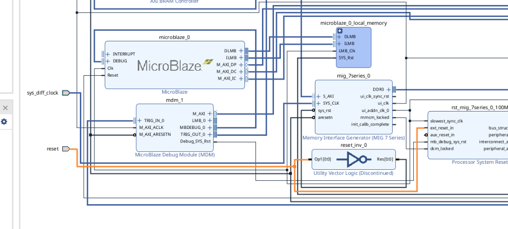
I opened my Block Design and saw that I had two reset pins for some reason:
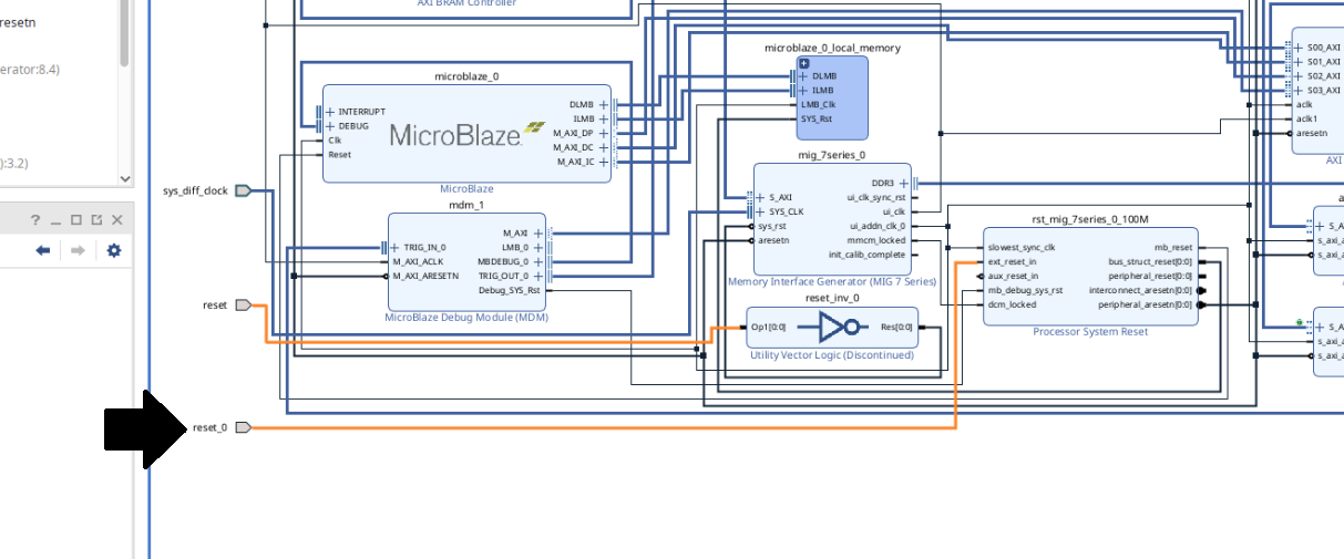
Removing the reset_0 pin and rerunning automation produced the same result and did not clear the error.
Removing the reset_0 pin and connecting the ext_reset_in port of rst_mig_7series_0_100M to the reset pin allowed me to clear this error and complete Step 7.
Follow Step 8
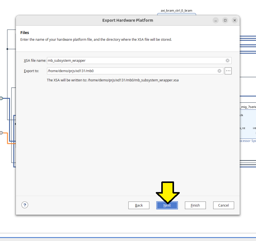
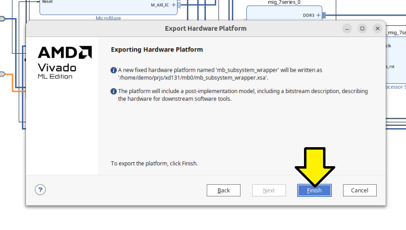
Continued with Step 8: Export the Design to the Vitis software platform.
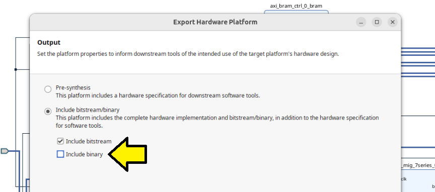
As part of step 8, I also included the binary in my hardware platform:
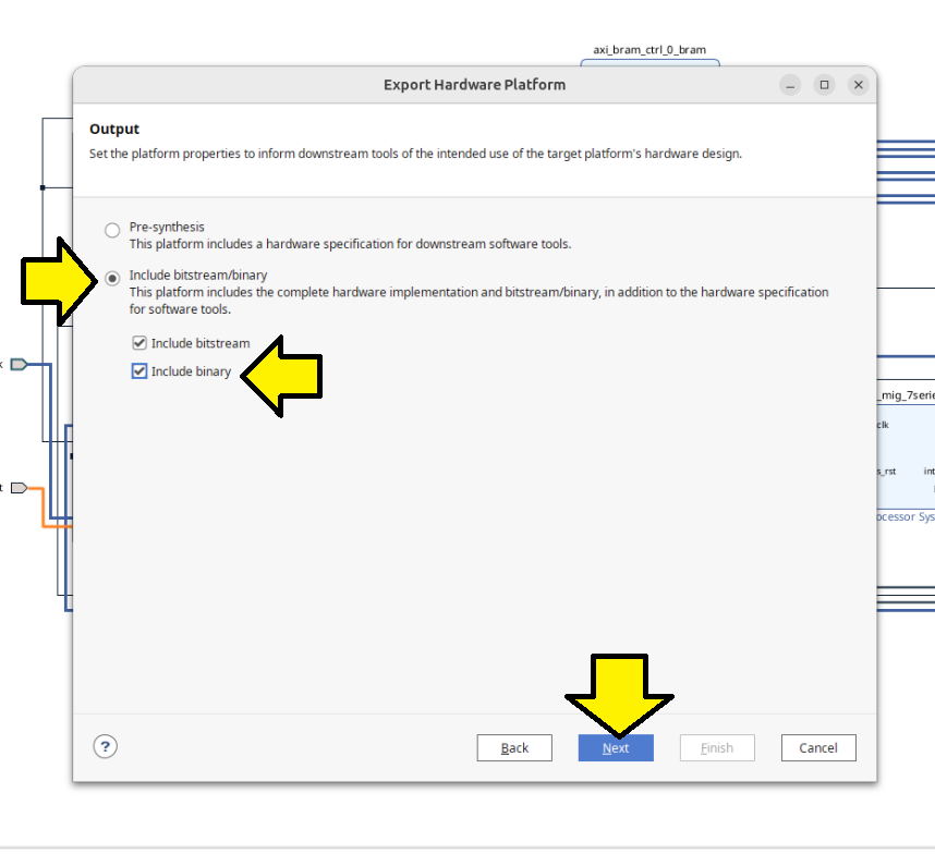
Saw an error:
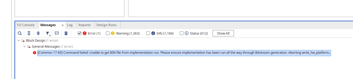
[Common 17-69] Command failed: Unable to get BIN file from implementation run. Please ensure implementation has been run all the way through Bitstream generation. Aborting write_hw_platform..
Regenerated without binary:
Launched Vitis
Follow Step 9
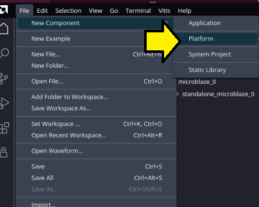
Continued on to Step 9: Create a “Platform Component”:
Saw:
This is not correct ^^^ and may explain the “PCIe” issue the user reported on the community forum.
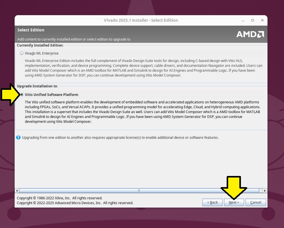
Reran my unified installer and upgraded to the Vitis Unified Software Platform:
/home/demo/amd/v20251_2/.xinstall/2025.1/xsetup
[!NOTE]
2025.1 is the last time AMD will release a full single file download aka standalone installer. See note.
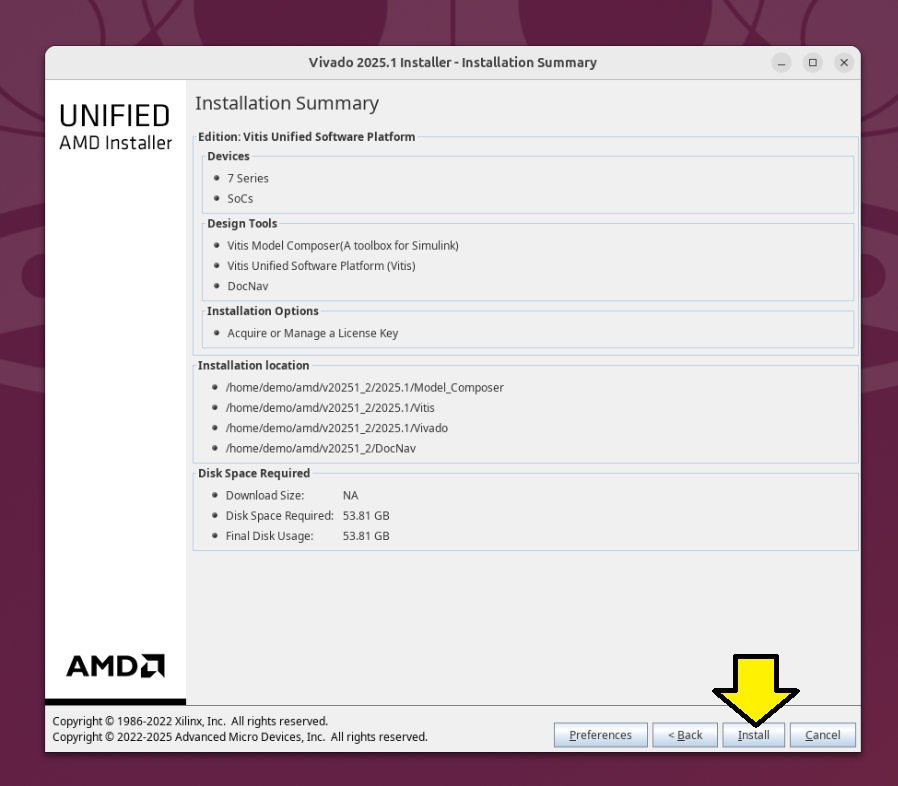
Selected Vitis Unified Software Platform and clicked **Next **:
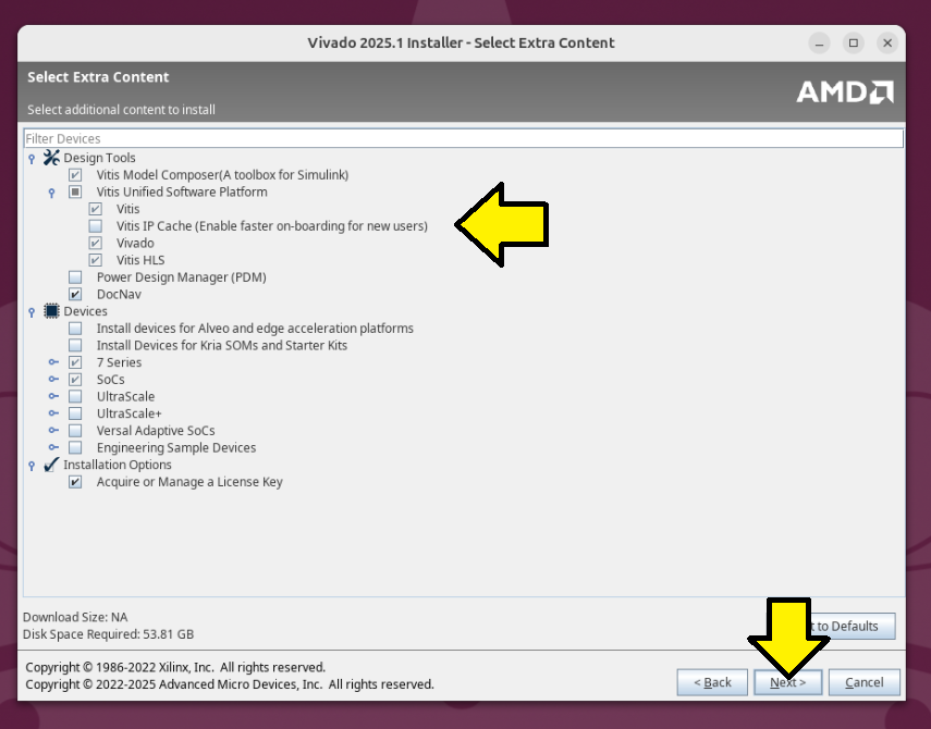
Used the defaults and clicked Next:
Design Tools
[ x ] Vitis Model Composer(A toolbox for Simulink) (can’t unselect)
[ x ] Vitis Unified Software Platform
[ x ] Vitis
[ ] Vitis IP Cache (Enable faster onboarding for new users)
[ x ] Vivado
[ ] Vitis HLS
[ ] Power Design Manager (PDM)
[ x ] DocNav
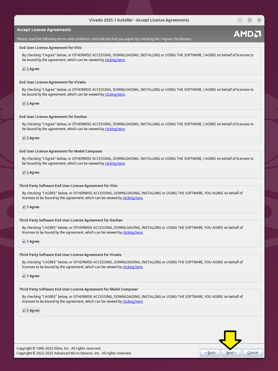
Agreed to all licenses:
Install:
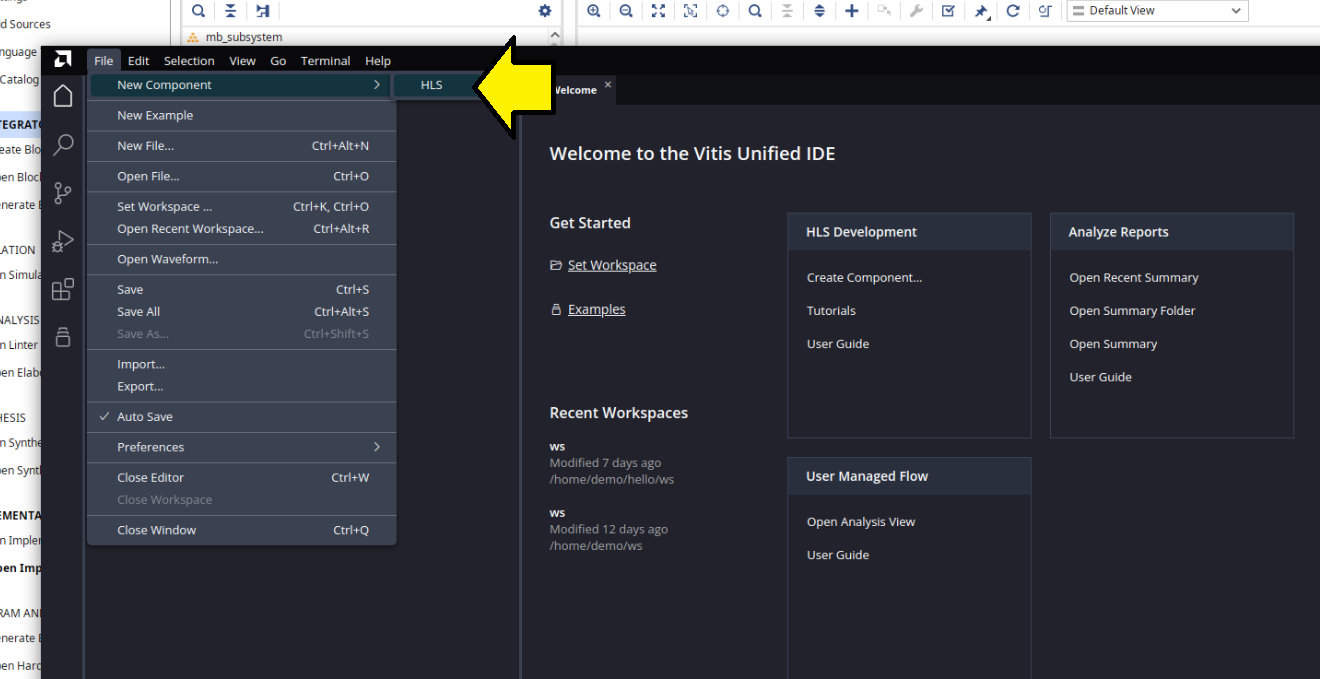
Reran Vivado, opened my mb0 project and launched Vitis again, Tools > Launch Vitis IDE and saw the same issue:
Checked:
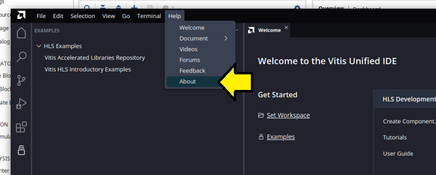
Saw:
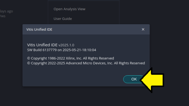
Launched a version of Vitis I installed in another location installed from the Vitis Embedded Development:
demo@demo:~/Desktop$ source /home/demo/amd/v20251/2025.1/Vitis/settings64.sh
demo@demo:~/Desktop$ vitis

****** Vitis Development Environment
****** Vitis v2025.1 (64-bit)
  **** SW Build 6137779 on 2025-05-21-18:10:04
    ** Copyright 1986-2022 Xilinx, Inc. All Rights Reserved.
    ** Copyright 2022-2025 Advanced Micro Devices, Inc. All Rights Reserved.
[!IMPORTANT]
In my experience now with 2025.1, launching Vitis depends on your installation. If you run Vitis from a Vitis Embedded Development install, you see different options than when you launch it from the Vivado install. This behavior is new in 2025.1. In 2024.2, selecting Vitis from the Vivado install gave you Vitis Embedded Development. Now, in 2025.1, it no longer does.
To install the Vitis Embedded Development, when the Unified Installer runs, select Vitis Embedded Development, not Vitis.
I suggest installing Vitis Embedded Development into a completely different directory from the Vivado install to keep it separate from Vitis installed by the Vivado installer or the Vitis Unified Software Platform.
Now I was able to select:
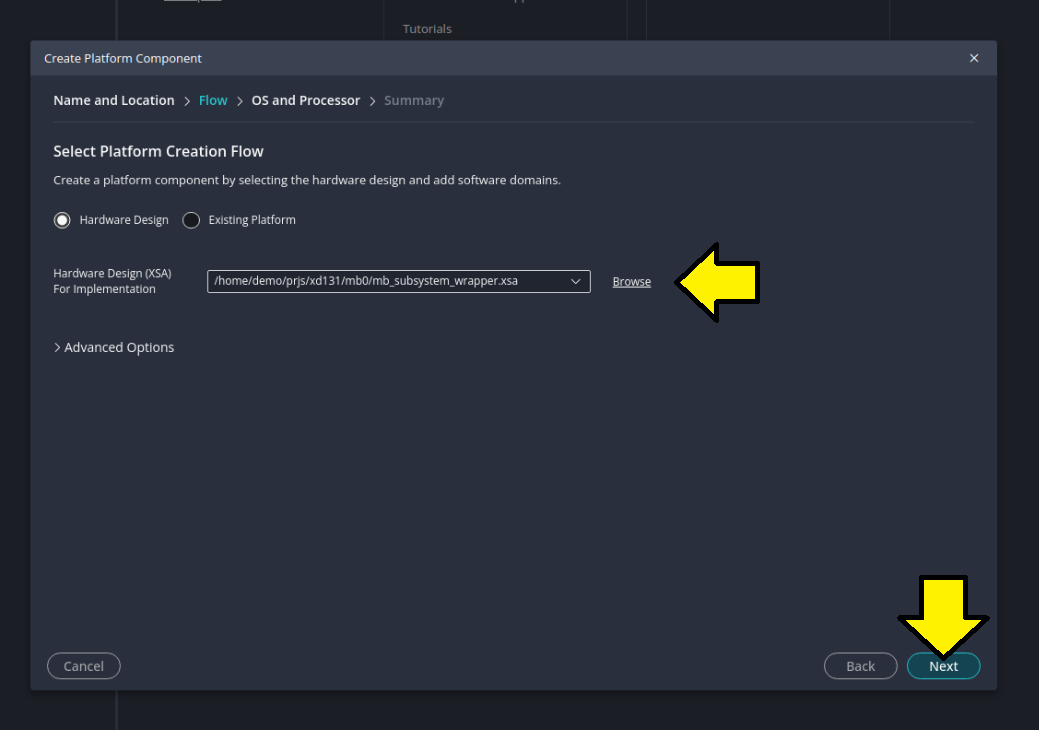
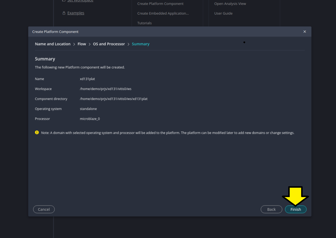
Continued with Step 9: Create a “Platform Component”.
Here were my last two screens:
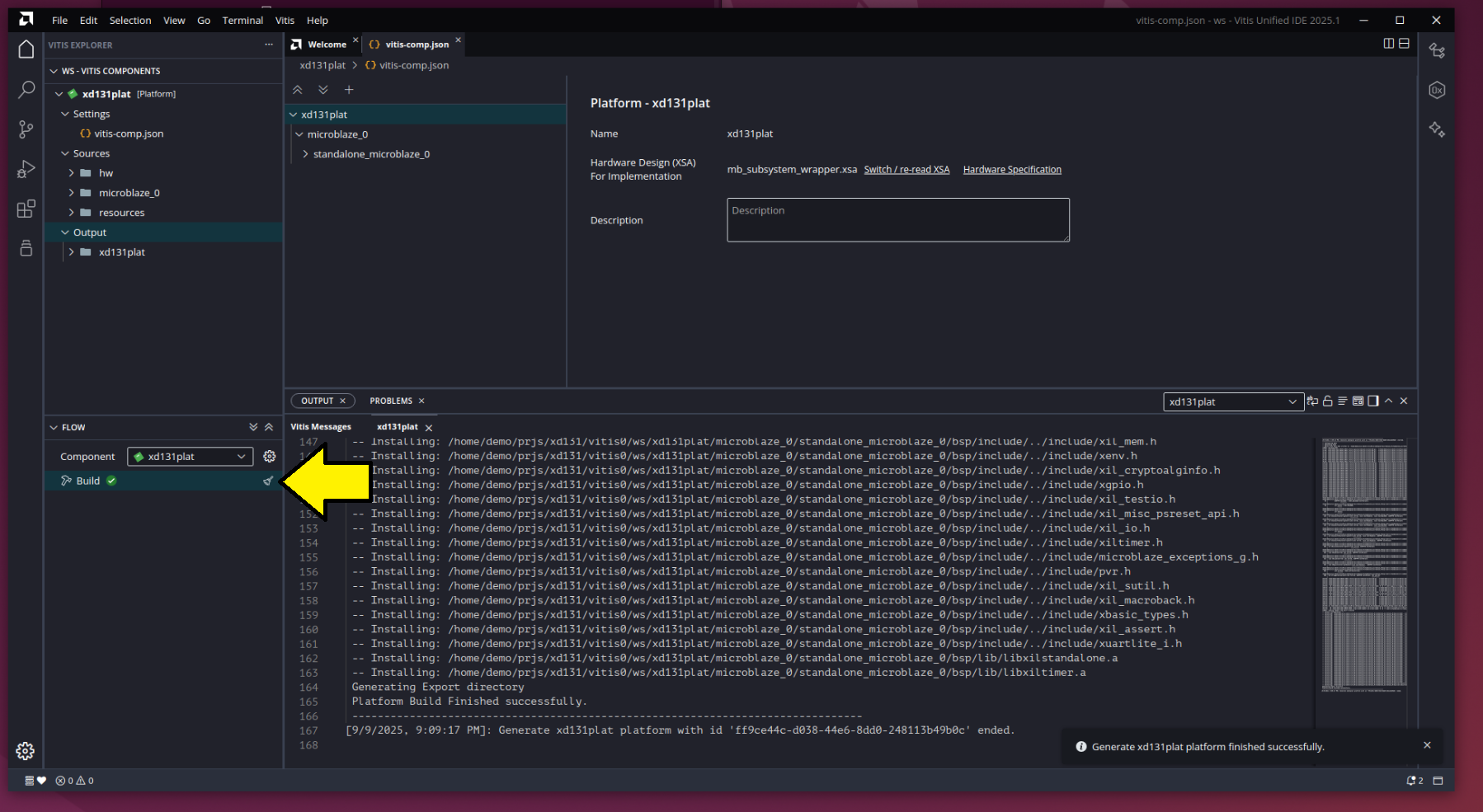
Saw a successful platform build
Follow Step 10
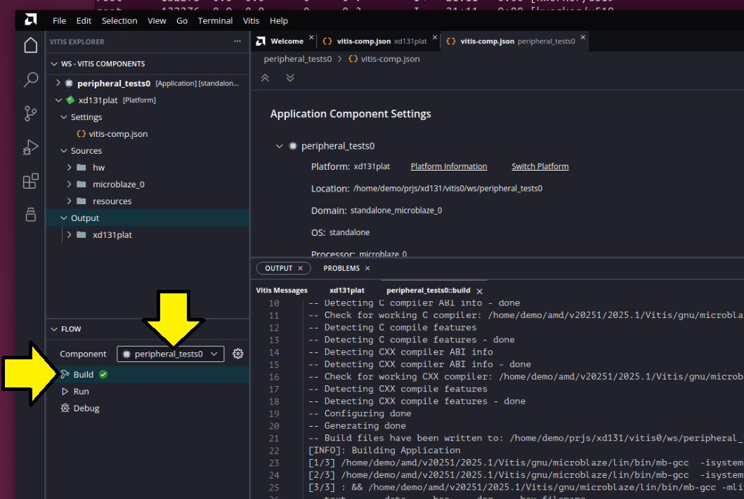
Continued with Step 10: Create a “Peripheral Test” Application.
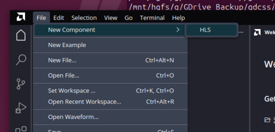
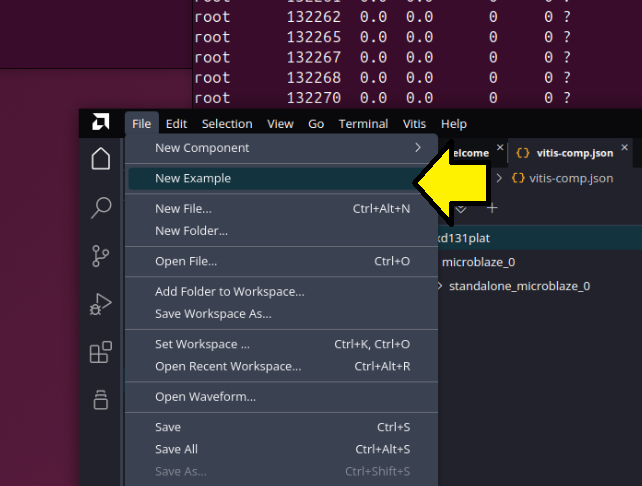
The path From Examples in Select File > New Component > From Examples or under Get Started click Examples did not exist. Selected File > New Example.
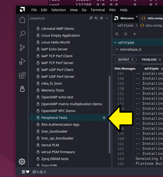
Added Peripheral Tests:
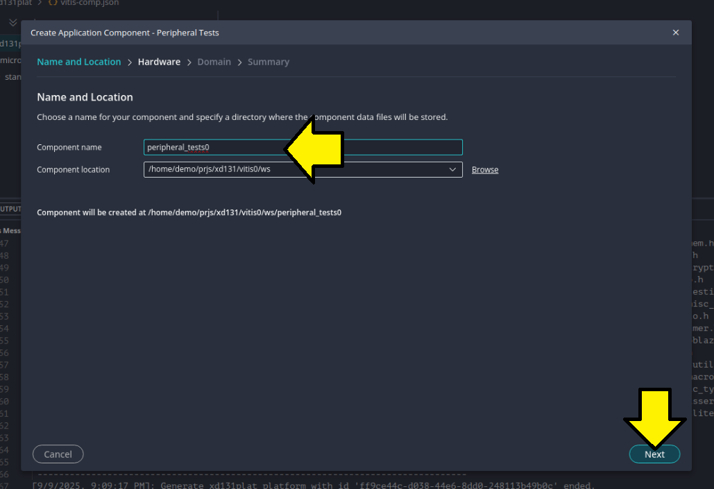
Named my component peripheral_tests0:
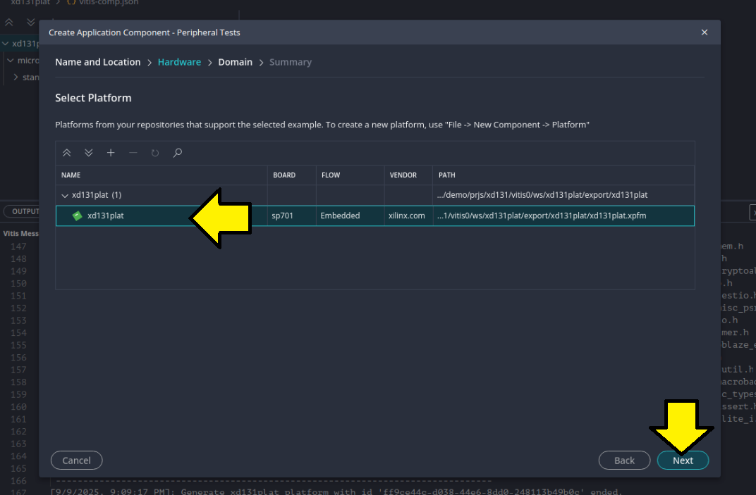
Selected the platform I built eariler:
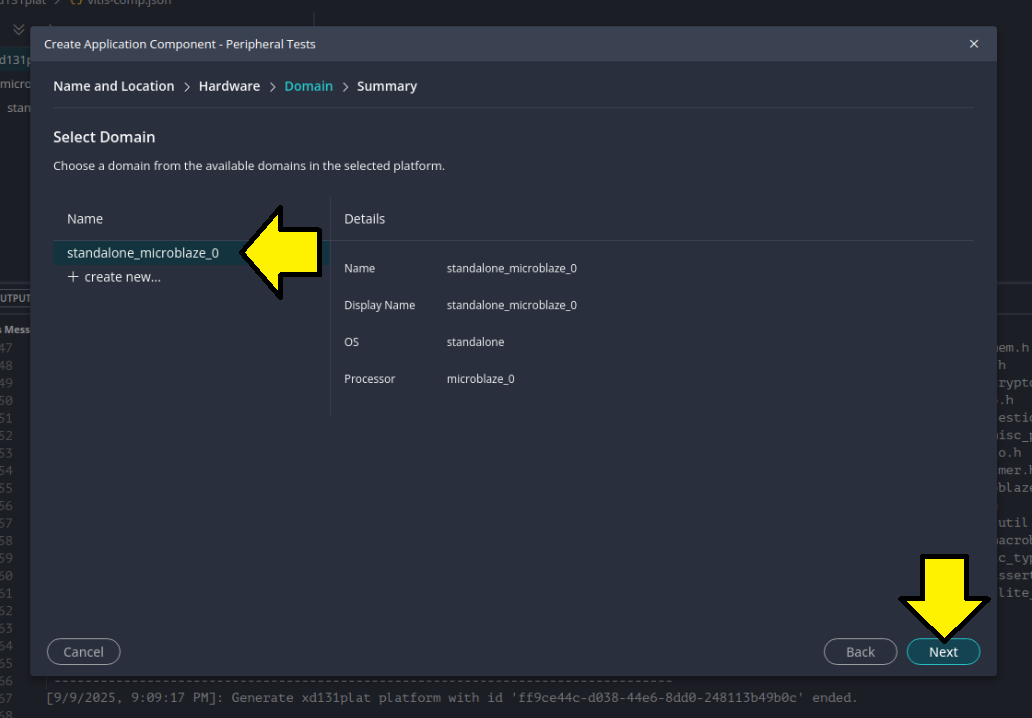
Selected the domain standalone_microblaze_0 and clicked Next:
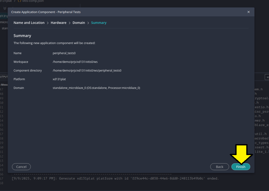
Clicked Finish:
Built and saw the build complete: